VESC hw_60 invert PWM.
Forums:
Hi, i building my custom VESC and i used inverting optocoupler to driving mosfets, so i try to modifiy init timers code in mcpwm.c as follow:
- Read more about VESC hw_60 invert PWM.
- Log in or register to post comments
Hi, i building my custom VESC and i used inverting optocoupler to driving mosfets, so i try to modifiy init timers code in mcpwm.c as follow:
When I received the FSESC 4.12 I connected it to the PC via USB, I updated the firmware and started the motor using the computer arrow buttons.
Today I tried to reconnect but the VESC Tool does not recognize the VESC.
The USB port is detected by Windows and when I remove power from the VESC I see that its USB port disappears from the management of Windows devices.
The COMM number is correct and the speed is at 115200.
But the VESC Tool does not communicate. The message is:
Hello all, especially those who may potentially be my saving grace. I received my EBESC 6.1 from eovanboard.com on sat and have been pulling my hair out try n to get this thing programed on the bldc tool. It seemes as though the motor set up went ok but i could not get the remote to connect to save my life seems as though i tried everything i could think of to no avail. can someone please help me, im about to go nuts! Thanks in advance!!
Hello Guys,
i would like to introduce my VESC-Design, which i ve made for my bachelors thesis. Its called SpaceVESC because it is used in our lab for the control of reaction wheels on a CubeSat test bench. The main benefit of this design is, that the logic-pcb can easily detached from the power-pcb. For our lab we want to use different power-modules in the future so we dont have to care about the logic part all the time.
Here is the schematic, which is like the vesc6:
Hi,
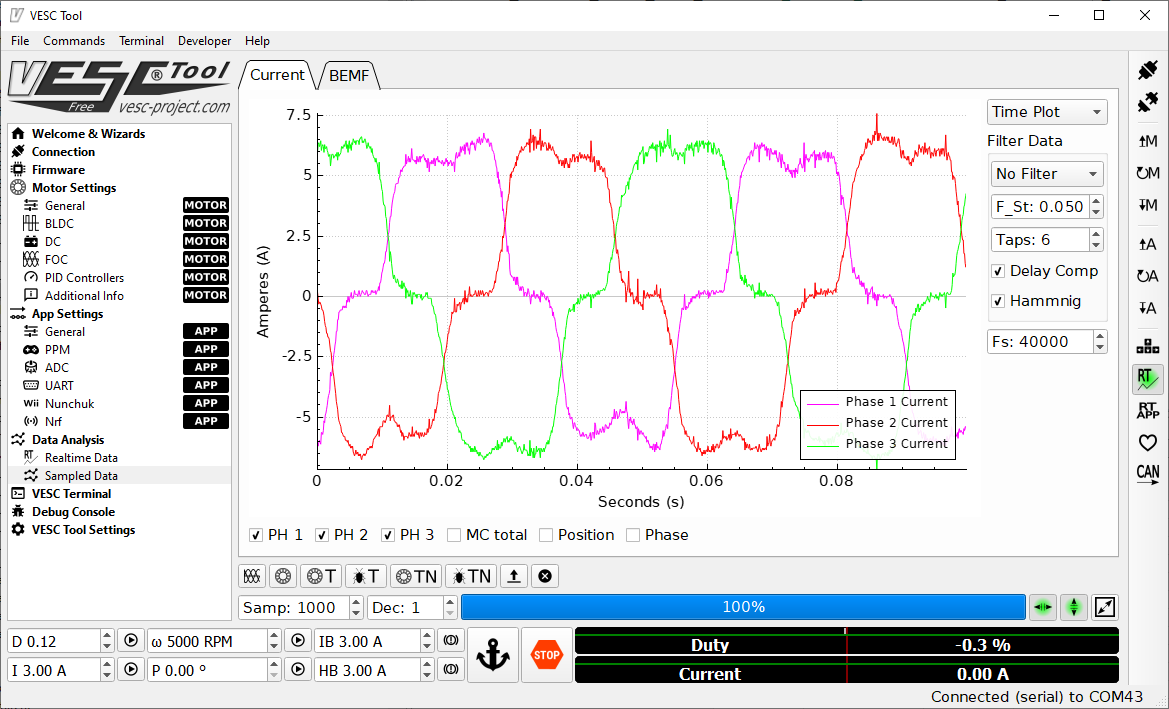
Im using 3 phase IGBT module.BLDC is working fine, but foc have strange current shape.
Also motor resistance measurement is wrong.(10mOhm on vesc , 50mOhm on IGBT module)
why current looks like this ?
Hi!
I wanted to try out VESC for a sensorless application and designed this:
https://drive.google.com/drive/folders/1hw-gLj4nVc55NpdjuklHnP325pea2THB...
This uses TO220 Mosfets - 150V and 20A.
So I was trying to program my Flipsky Dual FSESC6.6, I was able to program the left side just fine but then when I tried to program the right side it first said that "too old firmware..." well ok I updated the right side firmware but during the update it disconnected from the Dual FSESC6.6 and when I tried to reconnect it (after the 10-15sec. it needs to install the update) ,it just said "invalid serial port: \\.\COM3" in the right down corner. I even tried this with two different computers and three different USB cables and still the same results..
Hey,
We are working on a small project involving Flipsky ESC's programmed via VESC.
We just connected 2 different ESC's to the same motor and after connecting the 6 pin JST for hall-effect sensors (5v H1 H2 H3 0V) (Temperature not supported so left disconnected) we think it is bricked. We also plugged in 3 other wires (RX, ADC, -) to a stripboard with an Arduino on it.
So ever since the last 2 versions of the vesc firmware, I've noticed that the very first fraction of braking actually accelerates the board forward. If I lift the wheels off the ground and try move my throttle just the tiniest bit backwards to brake, I can actually get my wheels to spin forwards, then of course further backwards is braking as normal. I can feel this when riding. It's a little disconcerting when your board accelerates for a brief moment before braking. Any idea whats causing this?
Hi