I don't see an option to measure offsets in the mobile version of the tool. Is it possible there? I see it on the pc version but my stormcore is in a silicone beaded enclosure that I was hoping to avoid opening for a while. No problem if it is PC only, I can re-seal it.
Just found something a bit weird, not sure if its because of the new firmware or not.
My hardware is 2 low side shunt, with current and phase filters.
If I set 200A motor current and 20A battery current, this weird limiting happens and the motor slows down. I have a 20A power supply which is not limiting the current and the input voltage is solid.
If I then up the battery limit to 30A it reduces the affect.
Is that foc mode? I quickly checked the code in the foc algorithm and I did not see anything suspicious. If you are using foc mode, I will have a deeper look.
Is this going to get pushed into master at some point and made the main branch everyone uses?
I made some VESC compatible hardware, and for months struggled with motor screaming, random stalls resulting in violent braking and all manner of problems even though everything checks out perfectly on the hardware (loosely 100/250 based; I don't have that hardware so guessed what it was like based on the config file)... I put this branch on it a few days ago and suddenly... everything works perfectly... Even HFI works properly on a 5uH (1.5uH?) CA120-150kV motor.
There are substantial differences I have observed - the inductance measured on several motors I have tested varies by a factor of 2+, with the later code probably giving more credible results. The detection is far more reliable (previously I used to frequently fail detections on my custom hardware often and fail with FSESC 6.6 with skateboard size motors) but now it just detects with no issues.
Not sure if this is the panacea it seems or if you have other issues buried underneath this new one I am unaware of, but having seen the old firmware repeatedly put a 100+V spike back onto my 48V lab PSU while instantly locking the motor, only to have the same hardware perform very well with the new firmware... I feel like it might be time to make a new release widely available, and the updated tool referenced from the project with the ability to upload new firmware from it?
Update, having noticed that since I started writing the last post TechAmNu has been posting...
I also saw a strange effect at 200A - I set FOC openloop 200A and 300 speed whatsits... The motor span fine, board got hot very fast... But... Setting 250A only ever went to ~215A. Like TechAmNu, my PSU was not limiting, draw was about 300W @30V and the PSU is capable of about 500. I had set a battery limit of 20A. I thought not much of it, assumed it was PSU oddity related... but now reading someone else saw it as well...
What is the best way to measure and reduce the torque ripple I'm experiencing? Is there a way I can observe if this is instability in the current control. Is adjusting Kp and Ki the best way to reduce?
By the way, thanks for all the work that has gone into the 5.3 beta. I'm running beta 59 and the recent braking fix has eliminated a brake cogging problem I'd been experiencing in 5.2. This is great progress.
Can I make a feature request for a fast shutdown (whether option or always the case) for dealing with over voltage conditions? Asking following on from my insta stops experienced recently which I do not want to try to replicate...
This is clearly absolutely untrue. It is absolutely the case that where you have an ADC sampling at 15+kHz, a motor with a finite number of uH and you are not in the field weakenning regime, that you stand a very good chance of saving an overvoltage condition from destroying an ESC.
Say a typical scenario: 50uH motor, running at 55V with 60V FETs at 100A (e.g. an eskate with a 70kV 8080 motor and a VESC6 with 2*680uF is similar to this). Let's say you have 1000uF capacitance, and trip at 60V. If you're running much higher current than this with smaller caps, you are optimistic at best.
If we equate the energy 1/2I^2L with 1/2C(Vend^2-Vstart^2) we get a voltage rise of about 4V if the entire energy of the inductance ends up on the power rail. If we detect a few cycles too late and somehow manage to regen for a few cycles, then 100A charging the caps gives about 6.6V/PWM period, so we skip a period and then get all the energy from inductance... that's about 10V over voltage, which the MOS will easily survive, probably won't even leak much. It also equates to about 0.25J of energy, which is within the avalanche capability of most FETs we use.
If you repeat the math with 400A and 200uH motor, yes it gets tricky... but I am yet to discover one of these motors. My experience has been that bigger motors that can take more current scale down the inductance and in the end the total inductive energy that can possibly be stored scales with the mass of iron involved. I think you could generally over generalise and ask something like:
"Do my caps take up at least 5% of the volume of the motor?" If yes, then probably OK, fast shutdown will work well for non field weakening states.
But if you do nothing, carry on PWMing with a loss of synch, then the entire energy of the rotor/human/skateboard/truck kinetic ends up in the bus caps and it definitely becomes a fireball.
Is this realistic? Incidentally, I have tested this and observed roughly the results above, having written my own FOC code (which has very few of the features VESC has... just throttle input from PWM and ADC and torque control) just to learn and since I implemented this I have not had a single MOS or gate driver failure where I used to consider them consumable.
There are a few problems with the overvoltage protection when operating close to the maximum voltage. Currently it takes 8 PWM cycles to trigger the protection on over voltage:
Making it less than that will make it trigger a bit too easy on noise when operating close to the limit (on some hardware the measurement can jump several volts forth and back under high currents and/or when the environment is noisy). On the VESC6 the problem is that the DRV will die before the MOSFETs, as they easily take 10 or more volts above their rating before entering avalanche mode, even more when they are warmer. They are closest to their rating at -40C or so and the warmer they get the more voltage they will tolerate without starting to sink the current. The DRV will die just a few volts over 60V, so when the input is disconnected during full brake and the limit triggers at 57V, 8 cycles (16 if V0 and V7 sampling is not active) is more than enough to kill the DRV.
The situation is slightly different on the 75/300 and 100/250 as the other components can take 100V on the 75/300 and 120V on the 100/250. As the MOSFETs aren't so sensitive (they can sink the full current in avalanche for a few cycles usually) this gives them a higher chance of surviving a disconnect during full brake. That being said, I have seen them die from that too.
Conclusion: The firmware has some chance of protecting against overvoltage (which probably can be improved slightly), but the most effective way to not blow up the VESC is to make sure that the BMS does not disconnect the battery during full brake by using appropriate settings.
That being said, I can revisit this at some point, do some experiments and try to improve it, but I don't think there is much to gain. One improvement would be to ramp wrong_voltage_iterations down in the else instead of jumping straight to 0, which can help if the noise resets it frequently around the limit.
Can we not just keep the current way of doing this slow overvoltage detection set in VESC Tool. But then add a second fast trigger when it exceeds a value defined in the hw_conf, so you can have it immediately stop if exceeding the hardware limit which is not adjustable by the user. Kinda like difference between having slow abs_max_current limit set and not.
Also it would help if we get people out of the habbit of running all hw so close to the max voltage ratings.
Have you thought about replacing that code by some kind of belief filter? Basically, 61V as an overvoltage of 60V is a lot less credible than 65V, which itself is a lot less credible than 75V. And 63V followed by 57V is a pretty clear sign of noise, whereas 63V than 65V than 67V looks much more like a rising signal.
A Bayesian filter would be my first attempt to describe the problem, although it might be costly on the CPU. A simple way to approximate it might be an exponential weighting, for instance a filter driven by the square of differences. Maybe even a notch filter might be better, since the system's time constant is reasonably known.
It is maybe possible to get the 8 samples down to 2 or 3 samples, but that is still not guaranteed to save you. The 8 samples have saved me many times because the overvoltage was reached as the braking current was increased by the current controller and the input impedance was high due to using a power supply, a bad battery, or thin long cables.
The problem with the BMSes cutting the input is much worse. It is not that the voltage increases as the current controllers do their thing, it is the input being disconnected when the current already sits at the highest value. That is pretty much the worst you can do if you want to kill the controller. Not only is it the energy of the motor generating the full current and already increasing the bus voltage, there is also the inductive spike from the input cables the just got disconnected while carrying high current. That spike has so high frequency that is it likely to make it past the slow electrolytic caps and show up at the sensitive DRV. I have killed a 75/300 by the BMS cutting the input while drawing power (not generating), most likely because of this high frequency inductive spike.
Again, the situation can be improved a bit, the 8 samples can maybe be brought down to 2 or 3, but it is not guaranteed to save you. If you have a BMS that cuts the input under full load you are likely to destroy the hardware. Make sure to configure things so that this does not happen!
I'm not convinced that saying "it won't always work therefore not worth doing" is a good argument against it.
The problem isn't only present during BMS shut off. My experiences have been with PSU where for some reason it's lost synch or control or crashed or... And generated a massive spike. No brake request.
The DRV is a bit of a niche case, with most new hardware avoiding the fragile DRV. The short inductive artifacts from wire inductance could be avoided with ferrite and ceramic on the DRV supply, but also, the BMS will take most of that spike and the BMS FETs are usually arranged to have a fairly slow shutdown.
There's a few approaches you could take.
1) user setable depending on risk and application 1-8 cycles
2) Smarter filter that can shut down in 2 or 3 cycles
3) staged e.g. 8 cycles at 2 volts over limit 1 cycle at 10V... Maybe integrate the over voltage up to a limit?
I would be surprised if you couldn't dramatically reduce the number of VESC explosions with this. I guess killing a VESC 75/300 isn't such a big deal for you, replace a few FETs and it only cost you 60 euro or so in the first place but if I bought one and it dies that's potentially 400 euro loss.
I'm not saying it is not worth doing, I'm saying it is worth configuring your setup properly and that there is not much to gain here. I will still look into it and see if it can be improved a bit.
I would be surprised if you couldn't dramatically reduce the number of VESC explosions with this.
That is a very strong claim that does not align with my experience at all. In all the years I have been working on the vesc and blowing up hundreds of components, the difference between 8 cycles and 3 cycles would have saved me exactly zero times. There might be cases where that is not true, but as I explained, that does not align with my experience.
I guess killing a VESC 75/300 isn't such a big deal for you, replace a few FETs and it only cost you 60 euro or so in the first place but if I bought one and it dies that's potentially 400 euro loss.
Again, you are putting words in my mouth. You acting like this does not encourage me to listen to you exactly. There are a million other things I need to work on in the vesc software, and the last thing I want to put my time on is what the unpleasant guy from the forum is talking about...
Sorry to have upset you. I genuinely mean well. Please don't base your work on whether you like me and my attitude or not, do what is the best use of your time. I can modify that line of code in minutes if I so choose.
Yes it's a bold claim, but having written my own FOC code from scratch and thoroughly investigated this one I'm fairly confident. I blew up tens of MOSFETs before I added the lines of code that protects against over voltage and shuts down within about 30us and haven't experienced a single MOS failure since. I can't comment on DRV, and my number of samples is far far lower than yours. My code is nowhere near the sophistication and integration of yours but it has given me a detailed understanding and first hand experience.
I'll also add that for me, with my terrible code, this line isn't so much a hypothesis as a thing that actually saves me every single time I try anything new. Divide by zero and unstable observer is a normal day in the lab for me.
I'll bow out now. Thanks for the work and the new 5.03 ... It seems great. I was really excited to have HFI work perfectly the other day with virtually no setup.
It took some effort to make a setup where I can push the limit and reliably compare the algorithms against each other, but I managed to get some good results and the improvement is quite good. One interesting observation that I didn't realize before is that my 30A power supply seems to have quite a bit of internal capacitance and is able to sink some current. The new implementation barely made any difference on that power supply, but I got quite good improvements on my 5A power supply that sinks almost no current. On the 5A supply, applying full reverse on full speed with a fast current controller time constant made the voltage rise to 33V before triggering the fault with the old implementation when the voltage limit was set to 25V. With the new implementation, it triggered already at 27V under the same conditions, which is a good improvement. That might help with a disconnecting BMS in some cases and can hopefully save a few VESCs. But again, this is not guaranteed to help, so really make sure to get all settings right!
The new implementation works like the following: Use a voltage integrator and increase its value by the amount of overvoltage (v_in - l_max_vin). The higher the overvoltage is, the faster the integrator will increase. If there is no overvoltage, ramp down the integrator back to 0 with 1V per sample. When the integrator reaches 5% of the l_max_vin (2.85V with the default 57V limit on the VESC6) the fault is triggered and the integrator is protected against windup. This means that it can trigger even on one cycle if the overvoltage is 5% over the limit. If it only slightly exceeds the limit it takes much longer to trigger.
The builds in the first post are not updated yet, but I will do that later today. I still have to make some tests with the noisier old hardware versions to make sure that it does not trigger too easily.
Thanks very much for this and apologies again for any animosity I caused. I feel slightly guilty that I might have ruined your day... But hopefully not wasted it.
I spent a few hours flipping through the VESC code really trying to understand it last night, following through the flow from IRQ to writing PWM. One other area I noted (or perhaps is there but I couldn't find) was implementation of hard fault handlers, bus fault handlers... Maybe they're tied up in chibios I don't know.
A few weeks ago while tinkering I divided by zero and threw a motor across my desk. I managed to replicate the fault at low enough speed and voltage that it didn't cause a crash and found the debugger sitting in the while (1) of the st hard fault handler. I've now stuck a code line in it to disable the timer outputs in that condition.
I don't know what VESC/chibios does in that condition, or if that condition could ever or has ever been reached but maybe worth a thought.
No worries. I had a bit of a stressful day yesterday, sorry for being harsh. It was good looking into the voltage fault, there are probably a few situations where the new implementation can help. Doing the tests, getting some numbers and writing everything down was also useful.
I don't think I have done anything specific with the hardfault handler, it might be useful to look into that. There is a 12 ms watchdog that will cause a reset which should stop the timer and at least not throw the motor away, but disabling all outputs in the hardfault handler should reduce the current spike quite a bit.
Just testing on my revolt 160sh. 15V psu, voltage limit set to 20v. Going 95% -> full brake. -300A motor limit, -100A battery limit, 200us FOC PI.
OLD
25v
23.8v
25.3v
20.7v
NEW
20.6v
24.6v
22.2v
20.6v
21.0v
20.6v
22.2v
25.5v
Not sure there is much difference for my setup between the two versions, probably because there is a lot of bus capacitance. (similar to your PSU Normal results)
However, there is a very definite sound difference between the ~20v and ~25v measurements when running. Looking a bit closer it seems to be much worse when the duty cycle has gone negative?
20v trip, always has duty cycle +ve
Fault            : FAULT_CODE_OVER_VOLTAGE
Motor            : 1
Current          : -18.0
Current filtered : -18.3
Voltage          : 20.35
Duty             : 0.607
RPM              : 5486.3

Fault            : FAULT_CODE_OVER_VOLTAGE
Motor            : 1
Current          : -51.7
Current filtered : -51.4
Voltage          : 20.93
Duty             : 0.163
RPM              : 5464.1

Fault            : FAULT_CODE_OVER_VOLTAGE
Motor            : 1
Current          : -17.7
Current filtered : -20.7
Voltage          : 20.28
Duty             : 0.574
RPM              : 5491.3
25v trip, always has the duty cycle -ve
Fault            : FAULT_CODE_OVER_VOLTAGE
Motor            : 1
Current          : -114.3
Current filtered : 87.3
Voltage          : 21.42
Duty             : -0.950
RPM              : 5360.8

Fault            : FAULT_CODE_OVER_VOLTAGE
Motor            : 1
Current          : -96.7
Current filtered : 67.9
Voltage          : 21.14
Duty             : -0.950
RPM              : 5277.7

Fault            : FAULT_CODE_OVER_VOLTAGE
Motor            : 1
Current          : -99.2
Current filtered : 76.6
Voltage          : 21.22
Duty             : -0.950
RPM              : 5288.4
I've encountered an unexpected regen behavior on 5.3 beta 64. On startup, I have smooth and strong regen on a large ebike hub motor and a Raiden 7. After strong regen braking, the regen sometimes becomes much weaker, there is an audible noise, and the duty cycle (observed on android vesc tool) jumps around during braking. This weak braking torque and erratic duty cycle during braking persists until a power cycle and then returns to normal.
Thanks for the tip, I thought that an over/underflow might be a cause. All the values reported by foc_state stay around zero, except the phase values vary before and after the issue and shutdown but I didn't see an obvious pattern.
Another detail, I think I observed a couple times where it took multiple power cycles to get back to the expected behavior.
I'll try to see if the motor or battery regen current limits affect the behavior.
I'm familiar with the temperature rollback behavior on this bike. This braking issue happens on a cold motor and has other symptoms (high pitched noise, torque ripple, erratic duty cycle) that thermal rollback doesn't.
Another observation. The issue happens more frequently when the regen battery current maximum is less than the regen motor current maximum.
Also, the noise and torque ripple are apparent on positive throttle as well until a sufficient power cycle returns normal behavior for braking.
Is there a potentially corrupted variable that would affect both brake and throttle?
Now that sounds a bit like an issue with the offset measurement. If you get the problem, can you go to the FOC -> Offsets page and click Measure Offsets at the bottom?
However, there is a very definite sound difference between the ~20v and ~25v measurements when running. Looking a bit closer it seems to be much worse when the duty cycle has gone negative?
Can you try with a slower time constant and setting f_sw to 30 kHz? I think 200 uS was at the limit of working for me at 25 kHz, 30 was a bit better.
I also noticed that the full brake button will not ramp down the current nearly as fast as commanding a negative current. That is because it uses duty cycle mode with a somewhat careful pi controller in addition that ramps the current down before limiting the duty cycle. You can try using the current brake button with the full current.
Not sure there is much difference for my setup between the two versions, probably because there is a lot of bus capacitance. (similar to your PSU Normal results)
Funny, the power supply in the video that is on looks nearly identical to my "normal" 30V 30A power supply from the test.
I don't see the offsets changing before or after the behavior, but I'll keep looking. They are 2063, 2063, 2064 counts; 2.2, 2.1, -4.3 mV; 0, 0, 0.
Here is an image of the duty cycle oscillation. I provoked the issue and then ran the bike unloaded on VESC tool. The first trace on the left shows the oscillation (under throttle, coast, brake). Then I power cycled the vesc and the second trace shows the behavior in the normal state.
In both cases the motor was unloaded. I applied throttle, let it spin down, applied brake to stop, waited, applied brake to 0 rpm wheel. In the strange mode, I'm noticing duty cycle oscillations when I apply the brake when the rpm is zero and the motor makes the same high-pitched whine sound.
What beta version number does the firmware page show at the bottom?
5.3 Beta 60
What are the values on the foc -> offsets page? Can you try to run measure offsets and disable the calibration at boot?
I don't see an option to measure offsets in the mobile version of the tool. Is it possible there? I see it on the pc version but my stormcore is in a silicone beaded enclosure that I was hoping to avoid opening for a while. No problem if it is PC only, I can re-seal it.
Primary Side:
Current Offset 0: 1990.49
Current Offset 1: 1958.90
Current Offset 2: 2019.50
Voltage Offset 0: -0.0021 V
Voltage Offset 1: -0.0015 V
Voltage Offset 2: 0.0036 V
All Voltage Offsets Undriven are 0.0000V
Secondary Side:
Current Offset 0: 2020.35
Current Offset 1: 2009.76
Current Offset 2: 2013.79
Voltage Offset 0: 0.0047 V
Voltage Offset 1: -0.0023 V
Voltage Offset 2: -0.0023 V
All Voltage Offsets Undriven are 0.0000V
You can run foc_dc_cal from the terminal in the mobile version and read back the motor configuration a few seconds later.
Hi Benjamin
I set you a PM message with function I am looking for to be add to VESC.
Would you please look that and check how easy this can be add ?
Thx
Martin
Martin
Just found something a bit weird, not sure if its because of the new firmware or not.
My hardware is 2 low side shunt, with current and phase filters.
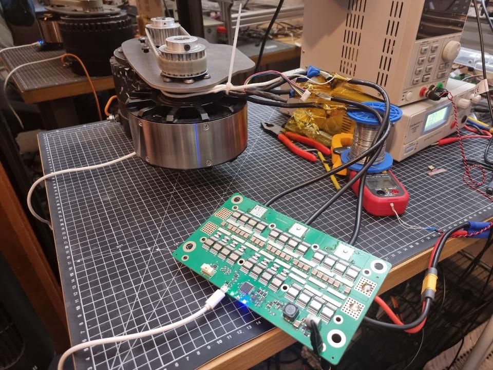
If I set 200A motor current and 20A battery current, this weird limiting happens and the motor slows down. I have a 20A power supply which is not limiting the current and the input voltage is solid.
If I then up the battery limit to 30A it reduces the affect.
50A battery limit removes the affect completely.
Do you want to tell something about that large speed controller A500S ?
Hi TechAUmNu,
Is that foc mode? I quickly checked the code in the foc algorithm and I did not see anything suspicious. If you are using foc mode, I will have a deeper look.
Yes its FOC, I haven't seen this before with older versions.
@Markula its A400S, 100v fets
I tried again with heavy load and it's actually starting to go backwards!
200A motor 10A battery with load
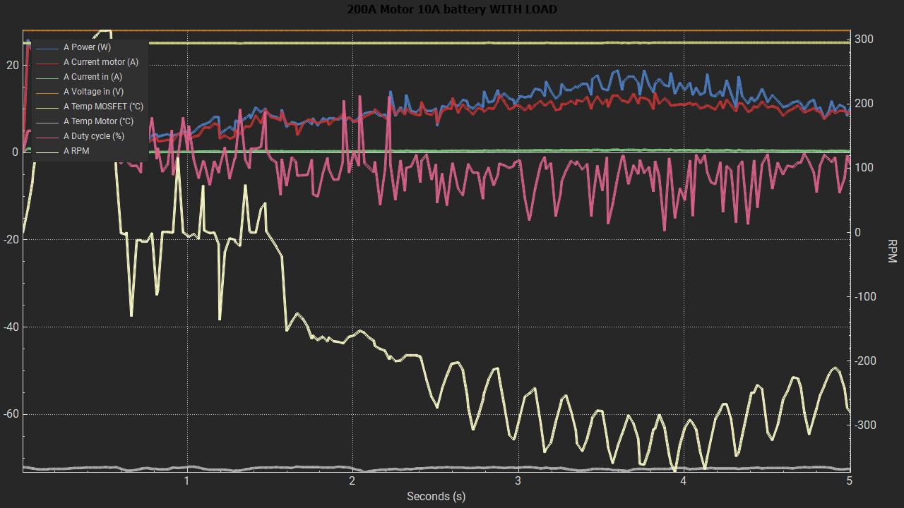
200A motor 20A battery with load
200A motor 50A battery with load. Limited a bit at the end by the psu current limiting and reducing the voltage.
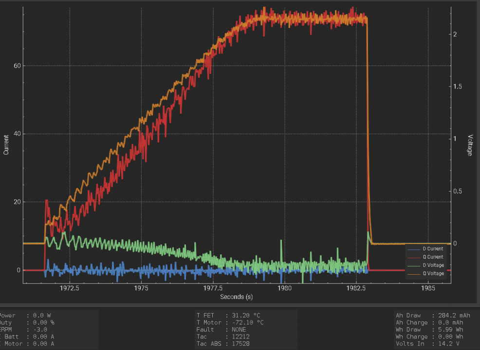
That is crazy. Can you also make some pictures of the FOC graph?
Do you use any feedback? Position/velocity pid?
10A battery
20A battery
50A battery
You don't use a BMS, do you?
And what do you use to generate that setpoint?
No just straight out of power supply. No other limits should be affecting it but the input current limit.
The sweep is done by the experiments tab, duty cycle sweep from 5% to 25% at 0.25s per 1%.
Checked all places where that parameter is used, but found nothing strange. I do not understand how that parameter can cause that behavior.
Hi,
Is this going to get pushed into master at some point and made the main branch everyone uses?
I made some VESC compatible hardware, and for months struggled with motor screaming, random stalls resulting in violent braking and all manner of problems even though everything checks out perfectly on the hardware (loosely 100/250 based; I don't have that hardware so guessed what it was like based on the config file)... I put this branch on it a few days ago and suddenly... everything works perfectly... Even HFI works properly on a 5uH (1.5uH?) CA120-150kV motor.
There are substantial differences I have observed - the inductance measured on several motors I have tested varies by a factor of 2+, with the later code probably giving more credible results. The detection is far more reliable (previously I used to frequently fail detections on my custom hardware often and fail with FSESC 6.6 with skateboard size motors) but now it just detects with no issues.
Not sure if this is the panacea it seems or if you have other issues buried underneath this new one I am unaware of, but having seen the old firmware repeatedly put a 100+V spike back onto my 48V lab PSU while instantly locking the motor, only to have the same hardware perform very well with the new firmware... I feel like it might be time to make a new release widely available, and the updated tool referenced from the project with the ability to upload new firmware from it?
Update, having noticed that since I started writing the last post TechAmNu has been posting...
I also saw a strange effect at 200A - I set FOC openloop 200A and 300 speed whatsits... The motor span fine, board got hot very fast... But... Setting 250A only ever went to ~215A. Like TechAmNu, my PSU was not limiting, draw was about 300W @30V and the PSU is capable of about 500. I had set a battery limit of 20A. I thought not much of it, assumed it was PSU oddity related... but now reading someone else saw it as well...
What is the best way to measure and reduce the torque ripple I'm experiencing? Is there a way I can observe if this is instability in the current control. Is adjusting Kp and Ki the best way to reduce?
By the way, thanks for all the work that has gone into the 5.3 beta. I'm running beta 59 and the recent braking fix has eliminated a brake cogging problem I'd been experiencing in 5.2. This is great progress.
Man, I think I finally found something. There is a feedback behavior that kicks in with the current battery limiting implementation.
Hacked the firmware a bit to trace mod_q and iq_target values. Since iq_target makes mod_q and mod_q is used in iq_target limitation, this occurs:
total current = iq_target
FOC phase = mod_q
zoomed in:
You cannot see this behavior in the other traces, they are way too slow for this.
Solved the problem by adding a tiny bit of low pass:
Will try to make a PR for this fix.
Without fix:
With fix:
Hmm made a mess out of my git stuff, still learning how it works. Maybe tomorrow I can submit the fix.
Ah that sounds like the right thing :D nice job finding it so fast! Looking forward to trying a fix.
I think I managed to reproduce and fix the problem. I also fixed the title color for the exported experiment plots. Can you give todays version a try?
Elwin, did we find the same thing? Just realized that you were working on it too :)
Haha, yes same problem same solution.
Working now with the fix! Graph title now readable as well :)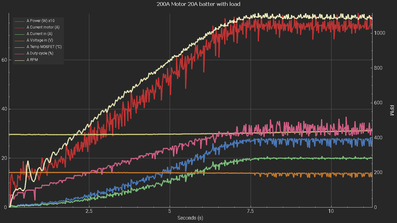
Benjamin,
Can I make a feature request for a fast shutdown (whether option or always the case) for dealing with over voltage conditions? Asking following on from my insta stops experienced recently which I do not want to try to replicate...
I just read https://forum.esk8.news/t/broken-trampa-vesc6-over-voltage/21429 where Frank is saying it is impossible to deal with the over voltage condition from braking while BMS disabled/...
This is clearly absolutely untrue. It is absolutely the case that where you have an ADC sampling at 15+kHz, a motor with a finite number of uH and you are not in the field weakenning regime, that you stand a very good chance of saving an overvoltage condition from destroying an ESC.
Say a typical scenario: 50uH motor, running at 55V with 60V FETs at 100A (e.g. an eskate with a 70kV 8080 motor and a VESC6 with 2*680uF is similar to this). Let's say you have 1000uF capacitance, and trip at 60V. If you're running much higher current than this with smaller caps, you are optimistic at best.
If we equate the energy 1/2I^2L with 1/2C(Vend^2-Vstart^2) we get a voltage rise of about 4V if the entire energy of the inductance ends up on the power rail. If we detect a few cycles too late and somehow manage to regen for a few cycles, then 100A charging the caps gives about 6.6V/PWM period, so we skip a period and then get all the energy from inductance... that's about 10V over voltage, which the MOS will easily survive, probably won't even leak much. It also equates to about 0.25J of energy, which is within the avalanche capability of most FETs we use.
If you repeat the math with 400A and 200uH motor, yes it gets tricky... but I am yet to discover one of these motors. My experience has been that bigger motors that can take more current scale down the inductance and in the end the total inductive energy that can possibly be stored scales with the mass of iron involved. I think you could generally over generalise and ask something like:
"Do my caps take up at least 5% of the volume of the motor?" If yes, then probably OK, fast shutdown will work well for non field weakening states.
But if you do nothing, carry on PWMing with a loss of synch, then the entire energy of the rotor/human/skateboard/truck kinetic ends up in the bus caps and it definitely becomes a fireball.
Is this realistic? Incidentally, I have tested this and observed roughly the results above, having written my own FOC code (which has very few of the features VESC has... just throttle input from PWM and ADC and torque control) just to learn and since I implemented this I have not had a single MOS or gate driver failure where I used to consider them consumable.
Thanks!
There are a few problems with the overvoltage protection when operating close to the maximum voltage. Currently it takes 8 PWM cycles to trigger the protection on over voltage:
https://github.com/vedderb/bldc/blob/dev_fw_5_03/mc_interface.c#L1735
Making it less than that will make it trigger a bit too easy on noise when operating close to the limit (on some hardware the measurement can jump several volts forth and back under high currents and/or when the environment is noisy). On the VESC6 the problem is that the DRV will die before the MOSFETs, as they easily take 10 or more volts above their rating before entering avalanche mode, even more when they are warmer. They are closest to their rating at -40C or so and the warmer they get the more voltage they will tolerate without starting to sink the current. The DRV will die just a few volts over 60V, so when the input is disconnected during full brake and the limit triggers at 57V, 8 cycles (16 if V0 and V7 sampling is not active) is more than enough to kill the DRV.
The situation is slightly different on the 75/300 and 100/250 as the other components can take 100V on the 75/300 and 120V on the 100/250. As the MOSFETs aren't so sensitive (they can sink the full current in avalanche for a few cycles usually) this gives them a higher chance of surviving a disconnect during full brake. That being said, I have seen them die from that too.
Conclusion: The firmware has some chance of protecting against overvoltage (which probably can be improved slightly), but the most effective way to not blow up the VESC is to make sure that the BMS does not disconnect the battery during full brake by using appropriate settings.
That being said, I can revisit this at some point, do some experiments and try to improve it, but I don't think there is much to gain. One improvement would be to ramp wrong_voltage_iterations down in the else instead of jumping straight to 0, which can help if the noise resets it frequently around the limit.
Can we not just keep the current way of doing this slow overvoltage detection set in VESC Tool. But then add a second fast trigger when it exceeds a value defined in the hw_conf, so you can have it immediately stop if exceeding the hardware limit which is not adjustable by the user. Kinda like difference between having slow abs_max_current limit set and not.
Also it would help if we get people out of the habbit of running all hw so close to the max voltage ratings.
Have you thought about replacing that code by some kind of belief filter? Basically, 61V as an overvoltage of 60V is a lot less credible than 65V, which itself is a lot less credible than 75V. And 63V followed by 57V is a pretty clear sign of noise, whereas 63V than 65V than 67V looks much more like a rising signal.
A Bayesian filter would be my first attempt to describe the problem, although it might be costly on the CPU. A simple way to approximate it might be an exponential weighting, for instance a filter driven by the square of differences. Maybe even a notch filter might be better, since the system's time constant is reasonably known.
It is maybe possible to get the 8 samples down to 2 or 3 samples, but that is still not guaranteed to save you. The 8 samples have saved me many times because the overvoltage was reached as the braking current was increased by the current controller and the input impedance was high due to using a power supply, a bad battery, or thin long cables.
The problem with the BMSes cutting the input is much worse. It is not that the voltage increases as the current controllers do their thing, it is the input being disconnected when the current already sits at the highest value. That is pretty much the worst you can do if you want to kill the controller. Not only is it the energy of the motor generating the full current and already increasing the bus voltage, there is also the inductive spike from the input cables the just got disconnected while carrying high current. That spike has so high frequency that is it likely to make it past the slow electrolytic caps and show up at the sensitive DRV. I have killed a 75/300 by the BMS cutting the input while drawing power (not generating), most likely because of this high frequency inductive spike.
Again, the situation can be improved a bit, the 8 samples can maybe be brought down to 2 or 3, but it is not guaranteed to save you. If you have a BMS that cuts the input under full load you are likely to destroy the hardware. Make sure to configure things so that this does not happen!
I'm not convinced that saying "it won't always work therefore not worth doing" is a good argument against it.
The problem isn't only present during BMS shut off. My experiences have been with PSU where for some reason it's lost synch or control or crashed or... And generated a massive spike. No brake request.
The DRV is a bit of a niche case, with most new hardware avoiding the fragile DRV. The short inductive artifacts from wire inductance could be avoided with ferrite and ceramic on the DRV supply, but also, the BMS will take most of that spike and the BMS FETs are usually arranged to have a fairly slow shutdown.
There's a few approaches you could take.
1) user setable depending on risk and application 1-8 cycles
2) Smarter filter that can shut down in 2 or 3 cycles
3) staged e.g. 8 cycles at 2 volts over limit 1 cycle at 10V... Maybe integrate the over voltage up to a limit?
I would be surprised if you couldn't dramatically reduce the number of VESC explosions with this. I guess killing a VESC 75/300 isn't such a big deal for you, replace a few FETs and it only cost you 60 euro or so in the first place but if I bought one and it dies that's potentially 400 euro loss.
I'm not saying it is not worth doing, I'm saying it is worth configuring your setup properly and that there is not much to gain here. I will still look into it and see if it can be improved a bit.
That is a very strong claim that does not align with my experience at all. In all the years I have been working on the vesc and blowing up hundreds of components, the difference between 8 cycles and 3 cycles would have saved me exactly zero times. There might be cases where that is not true, but as I explained, that does not align with my experience.
Again, you are putting words in my mouth. You acting like this does not encourage me to listen to you exactly. There are a million other things I need to work on in the vesc software, and the last thing I want to put my time on is what the unpleasant guy from the forum is talking about...
Sorry to have upset you. I genuinely mean well. Please don't base your work on whether you like me and my attitude or not, do what is the best use of your time. I can modify that line of code in minutes if I so choose.
Yes it's a bold claim, but having written my own FOC code from scratch and thoroughly investigated this one I'm fairly confident. I blew up tens of MOSFETs before I added the lines of code that protects against over voltage and shuts down within about 30us and haven't experienced a single MOS failure since. I can't comment on DRV, and my number of samples is far far lower than yours. My code is nowhere near the sophistication and integration of yours but it has given me a detailed understanding and first hand experience.
I'll also add that for me, with my terrible code, this line isn't so much a hypothesis as a thing that actually saves me every single time I try anything new. Divide by zero and unstable observer is a normal day in the lab for me.
I'll bow out now. Thanks for the work and the new 5.03 ... It seems great. I was really excited to have HFI work perfectly the other day with virtually no setup.
I spent all day on the overvoltage protection, and here are some updates:
https://github.com/vedderb/bldc/commit/f0b291d4eba62f9f99f1d0e265c86ffcb...
I also wrote a document about how I tested the new implementation and included some test results:
https://github.com/vedderb/bldc/blob/dev_fw_5_03/tests/overvoltage_fault...
It took some effort to make a setup where I can push the limit and reliably compare the algorithms against each other, but I managed to get some good results and the improvement is quite good. One interesting observation that I didn't realize before is that my 30A power supply seems to have quite a bit of internal capacitance and is able to sink some current. The new implementation barely made any difference on that power supply, but I got quite good improvements on my 5A power supply that sinks almost no current. On the 5A supply, applying full reverse on full speed with a fast current controller time constant made the voltage rise to 33V before triggering the fault with the old implementation when the voltage limit was set to 25V. With the new implementation, it triggered already at 27V under the same conditions, which is a good improvement. That might help with a disconnecting BMS in some cases and can hopefully save a few VESCs. But again, this is not guaranteed to help, so really make sure to get all settings right!
The new implementation works like the following: Use a voltage integrator and increase its value by the amount of overvoltage (v_in - l_max_vin). The higher the overvoltage is, the faster the integrator will increase. If there is no overvoltage, ramp down the integrator back to 0 with 1V per sample. When the integrator reaches 5% of the l_max_vin (2.85V with the default 57V limit on the VESC6) the fault is triggered and the integrator is protected against windup. This means that it can trigger even on one cycle if the overvoltage is 5% over the limit. If it only slightly exceeds the limit it takes much longer to trigger.
The builds in the first post are not updated yet, but I will do that later today. I still have to make some tests with the noisier old hardware versions to make sure that it does not trigger too easily.
Thanks very much for this and apologies again for any animosity I caused. I feel slightly guilty that I might have ruined your day... But hopefully not wasted it.
I spent a few hours flipping through the VESC code really trying to understand it last night, following through the flow from IRQ to writing PWM. One other area I noted (or perhaps is there but I couldn't find) was implementation of hard fault handlers, bus fault handlers... Maybe they're tied up in chibios I don't know.
A few weeks ago while tinkering I divided by zero and threw a motor across my desk. I managed to replicate the fault at low enough speed and voltage that it didn't cause a crash and found the debugger sitting in the while (1) of the st hard fault handler. I've now stuck a code line in it to disable the timer outputs in that condition.
I don't know what VESC/chibios does in that condition, or if that condition could ever or has ever been reached but maybe worth a thought.
No worries. I had a bit of a stressful day yesterday, sorry for being harsh. It was good looking into the voltage fault, there are probably a few situations where the new implementation can help. Doing the tests, getting some numbers and writing everything down was also useful.
I don't think I have done anything specific with the hardfault handler, it might be useful to look into that. There is a 12 ms watchdog that will cause a reset which should stop the timer and at least not throw the motor away, but disabling all outputs in the hardfault handler should reduce the current spike quite a bit.
Nice work on the voltage fault. Also like that you added the pdf with test results, very good!
Just testing on my revolt 160sh. 15V psu, voltage limit set to 20v. Going 95% -> full brake. -300A motor limit, -100A battery limit, 200us FOC PI.
OLD
25v
23.8v
25.3v
20.7v
NEW
20.6v
24.6v
22.2v
20.6v
21.0v
20.6v
22.2v
25.5v
Not sure there is much difference for my setup between the two versions, probably because there is a lot of bus capacitance. (similar to your PSU Normal results)
However, there is a very definite sound difference between the ~20v and ~25v measurements when running. Looking a bit closer it seems to be much worse when the duty cycle has gone negative?
20v trip, always has duty cycle +ve
25v trip, always has the duty cycle -ve
Video showing effect
I've encountered an unexpected regen behavior on 5.3 beta 64. On startup, I have smooth and strong regen on a large ebike hub motor and a Raiden 7. After strong regen braking, the regen sometimes becomes much weaker, there is an audible noise, and the duty cycle (observed on android vesc tool) jumps around during braking. This weak braking torque and erratic duty cycle during braking persists until a power cycle and then returns to normal.
Can you type foc_state in the terminal after it happens before doing a power cycle? It could be that some values turn into NaN or INF.
Thanks for the tip, I thought that an over/underflow might be a cause. All the values reported by foc_state stay around zero, except the phase values vary before and after the issue and shutdown but I didn't see an obvious pattern.
Another detail, I think I observed a couple times where it took multiple power cycles to get back to the expected behavior.
I'll try to see if the motor or battery regen current limits affect the behavior.
Could it be that the motor got too warm and ran into the temperature limit where it decreases the current limits?
I'm familiar with the temperature rollback behavior on this bike. This braking issue happens on a cold motor and has other symptoms (high pitched noise, torque ripple, erratic duty cycle) that thermal rollback doesn't.
Another observation. The issue happens more frequently when the regen battery current maximum is less than the regen motor current maximum.
Also, the noise and torque ripple are apparent on positive throttle as well until a sufficient power cycle returns normal behavior for braking.
Is there a potentially corrupted variable that would affect both brake and throttle?
Now that sounds a bit like an issue with the offset measurement. If you get the problem, can you go to the FOC -> Offsets page and click Measure Offsets at the bottom?
Can you try with a slower time constant and setting f_sw to 30 kHz? I think 200 uS was at the limit of working for me at 25 kHz, 30 was a bit better.
I also noticed that the full brake button will not ramp down the current nearly as fast as commanding a negative current. That is because it uses duty cycle mode with a somewhat careful pi controller in addition that ramps the current down before limiting the duty cycle. You can try using the current brake button with the full current.
Funny, the power supply in the video that is on looks nearly identical to my "normal" 30V 30A power supply from the test.
I don't see the offsets changing before or after the behavior, but I'll keep looking. They are 2063, 2063, 2064 counts; 2.2, 2.1, -4.3 mV; 0, 0, 0.
Here is an image of the duty cycle oscillation. I provoked the issue and then ran the bike unloaded on VESC tool. The first trace on the left shows the oscillation (under throttle, coast, brake). Then I power cycled the vesc and the second trace shows the behavior in the normal state.
Did you try to re-measure the offsets and not do a power cycle? They will not change by themselves, but they can be measured badly at boot.
Can you log the data when it behaves badly as well as when it behaves well and post the log? You can activate the log here:
It will create a file in the a directory called log where vesc tool is run from by default.
Thanks for the idea. Measuring the offsets does not resolve the issue. The only resolution so far is a power cycle.
Couldn't figure out how to attach files, so here are links.
Log file for strange behavior: https://gist.github.com/dsoto/c513a73215ccc81916f262f24c14b5f5
Log file for normal behavior: https://gist.github.com/dsoto/e4acac41151e21968dcca8cda296dda0
In both cases the motor was unloaded. I applied throttle, let it spin down, applied brake to stop, waited, applied brake to 0 rpm wheel. In the strange mode, I'm noticing duty cycle oscillations when I apply the brake when the rpm is zero and the motor makes the same high-pitched whine sound.
Looks really strange.
Can you try uploading this firmware from the custom file tab on the firmware page?
http://home.vedder.se/tmp2/vesc_raiden7_2021-11-14.bin
If it does not work, can you post the output of foc_state in the terminal after it becomes noisy?
Pages