Hi, I cant find the right firmware there. Which VESC Tool Version do you have? I got Version 1.16 and it tells me to update the Firmware of the A200S to Version 3.58 and it only supports that version which kinda sucks.
@jlcortex Means FOC works much better with phase shunts.
In other news I found a spectacular bug in the hardware that was probably causing all my issues at higher voltages!
For some reason I added a 2.2uF capacitor on the voltage divider that measures the supply voltage. Which makes the frequency response of that voltage divider absolutely awful. This means that when you have hard regen braking, the bus voltage is actually significantly higher than what the ADC measures so it will keep braking too long and blow everything up.
Simple fix for this, remove C1.
All the new boards have a TVS diode on each phase, from the supply side of the ceramic caps directly to the battery ground cable. Combined with the removal of this pesky cap it should be good for higher voltages. The TVS diode is this one https://uk.farnell.com/littelfuse/1-5ke75a/tvs-diode-1-5kw-64-1v-unidir-do/dp/2777092 which has a breakdown voltage between 71.30-78.80V, obviously adding the TVS means no 18S support, but I am going to be doing some testing at 18S again to see what difference removing the cap has. It might be that the TVS are not required depending on how fast the over voltage error turns off the fets.
Here you can see how detrimental the capacitor is. The main problem here is that the overvoltage warning will trigger FAR too late to do anything helpful.
Unless you have bricked the bootloader you should be able to update it over USB, the firmware has almost made it into VESC Tool which should make updating a bit easier.
In some cases over voltage protection is not fast enough. Have been playing with 100V setup with LAB power supply which has low output capacitance and accidently pressed regeneration button, consequences - two blown FETs, one on low side, one on high side. Over voltage protection was set on 105V, FETs used 150V so in total 45V difference was not enough to protect the FETs.
I'll to will try to do some testing with this protection.
Yeah it really isn't good enough to rely on for protecting the fets, we need reaction time in order of a few uS at most so hardware protection would be best.
That's why I decided to add TVS diodes so there is at least something that tries to protect the fets.
I have 100v fets and set max voltage to 70v, with TVS kicking in at about 72v.
Yeah i fought about hardware protection too, but you have take some sacrifices then doing small factor ESC.
If you have enough capacitance software protection should be fine, bad things could happen than you hit regeneration on fully charged battery pack, in this case electrolytic caps should help. It's not hard to calculate the capacitance needed.
I'm thinking adding a tvs diodes to, but doesn't decided is it necessary. Those ones that you chose is pretty fast, I like them.
Had done some crazy testing today, was trying to blow some FETS. All of that is just to decide if scope is showing noise or real voltage spikes then FETS are switching. Managed to get spikes over 30V of fet nominal voltage and fets didn't blown up (FLIR not showed any heating signs to), so I'm assuming that what scope shows is just a noise. Maybe adding those tvs diodes would clear out things further.
You are so lucky if you are blowing just one fet, usually I get 2 blown fets. Will try to use faster fuses to prevent that (want no plasma balls any more).
If you are getting lots of noise, make sure to use the little spring that goes on the end of the probe, or solder a coax directly to the board, get as close as possible to the supply and ground across the fet. When I measure I do it across the ceramic capacitors that are directly on top of the fets so the whole loop area is only a few mm including the fets.
I might add hardware protection at some point but for now doesn't seem necessary as long as you are reasonably sensible with settings.
At the moment I am working on an even smaller version for mass production, should be doing a batch of 100 in about a month. Main change is to take off a shunt per phase and the press fit terminals, so its now 2x 500uOhm. So max current measured will be 330A. Saves a lot of space removing the terminals and means the case can be better sealed with just holes for wires to pass through.
I also changed the input connections from 3x XT90 with 10AWG to 3x XT60 with 12 AWG. Which cuts down unnecessary weight quite a lot. The maximum battery input is set to 180A so the XT60 should be fine.
Wow, looks awesome, size and specs are too!! Gosh those 3D visualizations looks so great, maybe it's time to change old 2004 pcad to something newer!
I'm fixing all my bugs in driver board and planing too add a hardware protection for over-voltage if it turns out that TVS diodes can't handle it. Probably will do some testing with 100V today after parts arrive for my damaged 5kW power supply.
Yeah I had considered out terminals just because they are so beefy and there is no real benefit for using them.
Those are a TVS diodes near electrolytic caps? You used 3kW or 5kW? Ordered a few 5kW ones.
Can you tell what are approximate costs for 3D printed case and aluminum heat sink? Still haven't decided which path to go - make a more complex heat sink and cover it with a PCB (like Vesc 6) or make a simple heat sink and more complex plastic cover with 3D printer (preliminary cost 45 Euros).
Depends a lot on quantity, probably about 30-100usd for a machined heatsink at 1-5off. 3D printing case is pretty cheap if you get PLA or ABS about 10-15usd, mine are MJF Nylon12 which is quite pricey even at 100off. For a single part though MJF about 40usd.
I just received my A200S and was happy before I accidently ruined it… ☹
I connected with the VESC tool app and it told me that communication was limited due to old FW. I updated the FW trough the app but I probably chose the wrong board or something because it’s not booting up after this.
Could you please provide a compiled FW for me? I have a SWM programmer and I am able to connect, but I don’t know how to compile a FW from github.
I think that I can fix it if you give me the correct hex file.
I noticed you can now get 2 layer metal core boards quite cheap, so for the first set of new units I have ordered half with metal core and half normal FR4 to compare the difference.
Reading on the metal core gives me numbers about 400A for a 3oz 6mm wide track and 60A for a 0.3mm via! That is mental.
I have been running 400A at 100v while bench testing my 24F controller with one layer Al substrate 3oz used for the power stage. Plus copper strips for reinforcement. I think metal core is the **right** way to go with SMT mosfets. FR4 and high amp SMT mosfets just don't mix well together. You'll be dealing with a lot of heat issues.
I got mine from PCBWAY, they will do single layer or dual layer metal core boards with the metal on either one side and both layers stacked on top, or on either side of the metal with insulated vias going through it.
Here are some pictures,
the black board is 5oz FR4, matt black, ENIG
green board is 3oz metal core, green, HASL - You can see that I had to reduce the number of vias to stop them from shorting as they went through the metal. To give you a via, they will drill a bigger hole and insulate it, then drill again and finally plate it.
I was setting up 200A esc and had a problem. I was able to connect. Then I uploaded the appropriate firmware. After that I was able to start programming. In the FOC wizard when I ran detection, the motor made no noise and the following message was displayed: "Detection failed. Reason: Sensor detection failed." Am I missing something simple? Everything is plugged in and I've triple checked the wiring. Any help would be appreciated. Thank you.
Are you getting any data under Real Time Data tab when RT button is pressed and the controller is connected? If so, check the fault code and the battery voltage it's reading.
The first thing I do with a new controller is set the voltages right. The default value are set 57v max and my battery pack is a way above that, so overvoltage fault triggers and that prevents detection from working.
I am getting realtime data. The fault code says "Overcharge". The Battery voltage reading is 60v on the money. I'm using a 16s8p battery.
When I try to do the FOC wizard I get the result that I mentioned above, but when I do it under the FOC tab, the motor hums and turns a little bit. Then it returns a message saying that "R is 0. Please measure it first." I thought that it was doing that for me.
You mean "Overvoltage"? Go to the General->Advanced tab and bump up the input max voltage to 61v or whatever your highest voltage is on the battery. Hit write motor configuration. You should be able to run detection after that. Just make sure Fault in the Real data tab says "None".
Thank you for your help. We're making progress. The wheel spins up now, but a few seconds after that, the ESC disconnects. R and L detection works but then when it checks the lambda the problem happens. There is a message saying that the detection failed because the ESC disconnected during detection. Do you have any idea why that might be?
You may need to adjust the current (amps) in the detection dialog before you attempt to detect the flux linkage. It spins the motor in open loop and sometimes need specific amps to attempt to spin the motor in open loop. I would try values between 10-30amps. Also, this is very much specific to the motor, so it would help to know what kind of motor you are running.
The motor is 60v 1600w. It has is rated for 50A continuous current. I think that I understand what you are talking about above. I mess with it. Thank you again.
I've meddled with the current and erpm. There has been some difference, but for the most part during the flux linkage part it still disconnects. During the initial detection the observer gain does not get calculated. Is it supposed to?
I am hoping you raised it off the ground and trying to free spin it with flux linkage detection unloaded? It sounds like something is blocking it from free spinning it.
I just restarted everything and suddenly it worked. I had tried this before and it didn't. I don't know exactly what happened, but it's running smoothly. Thank you.
Define aggressive performance. I am guessing fast acceleration from 0rpm. Is that bad or good? Most people think it's great and it's one big thing that sets EVs apart from ICE vehicles.
However, you can in fact adjust your acceleration if you like by dropping motor amps and/or changing the throttle input curve.
Acceleration, top speed and braking power.. Honestly, I'm not too concerned about top speed. This motor can go far faster than I'll ever need ot go. I'll play with the amps and motor curve a bit to see what I an do about things like acceleration.
Just drop the battery and motor current by 1/2 of the present settings if they feel too violent. Make sur to use FOC and Current control mode. That provide the most natural throttle response on a bike very similar to a gas bike throttle response.
Don't use duty cycle or PID speed for your application.
So I got my new boards in now, but having some issues with oscillation on the gates. I took a video running in DC mode to show what happens.
DC mode holds one leg down then pulses the other high to reach the wanted current. I was slowly increasing the current each time, after about 25A it starts to get bad enough to cause big problems.
One interesting thing was doing it constantly was not a problem but leaving it for a few seconds and trying again made it much worse.
Any ideas? Thinking adding a cap on the gate might help. I already tried gate resistors about 8 ohm, 0 ohm and 1.6ohm video is with 1.6 ohm fitted.
A clear gate route layout picture would help here to confirm that's likely the issue. You can mitigate that however with higher gate resistance values. 1.6 or even 8ohm is too aggressive in most cases. You need nearly perfect gate routes with that. Try at least 10 or better 20 Ohm. Caps might work if you are lucky enough but you need to make a good guess with the value. I've tried 10nF with my design and it made it worse.
Low side, with 1R6 gate resistors this looks really good and clean. No ringing at all. It is far away from the current path and perpendicular to it so should be fine.
High side, i think the problem is caused by the quite long section parallel to the current path. Capacitors were added between the pins on the connector and right at the end of the gate signal trace.
Before adding caps, spectacular ringing causing mosfets to turn on and off. Frequency of the ring is about 50MHz.
Measured using spring ground on probe.
After adding caps (2x 22nF), much better but still there, going to replace gate resistors with ferrite beads.
Measured using spring ground on probe.
Output is now clean, ringing on highside edge is caused by long probe ground lead.
That makes sense that the low side behaves much better because the gate path is super short. The high side is like 6x longer and it's wiggling between high current paths. You want them to have the same length and symmetric. The return path ideally needs to be right under the gate route and nothing under it. I know it's hard to do with two layers. I also use two resistors per side. One larger near the the gate driver and one smaller value very close to each mosfet. This is to deal with the ringing.
Thank you for your help. I've done all of these things and a bit of testing. I can get the motor to roll and break on pavement, but on level dirt, I'm at a stand still. There are sounds, but I'm not going anywhere. The 60v 1600w motor with a kv around 30 should get going on level dirt. I'm either missing a vital setting or the battery isn't living up to expectations. It's a 16s8p 21 Ah battery with a 50A BMS. I'm hoping there is a simple solution to this problem. Thank you again for taking the time to help out.
Post your configured settings, at least, from th Motor->General tab. It makes no sense that it runs on pavement but not on a dirt road. Have you tested it under load (with you being on the vehicle)? How is it accelerating? I thought you mentioned it was too fast for you.
That battery is shady. Be wary of stuff from Aliexpress, especially batteries, and especially when they don't name the specific cell brand and model used to make a pack. Because they don't name the brand, like Panasonic/Sanyo or Samsung, I would have to assume the worst which would be Chinese brand which can be really bad. It's unlikely to be the pack though, even if it's subpar. 8 in parallel should give you at least 20-30A which should be enough to push a bike. Check if the voltage drops when you try to accelerate and how much it drops. But most likely, it has to be something with the controller configuration.
Do you know the best way to upload pics here? When I try to upload pics, it just asks for a link. I have screen clips of the motor->general settings. At the bottom I have included links to data gathered using a metr pro Bluetooth dongle that I have. The first data set is from an unloaded bench test. The second from blacktop while loaded (with me). I could not push full throttle here for safety sake. The third is from dirt while loaded. I was able to push full throttle. The motor made noise and tried to go, but couldn't.
The dirt that I am testing in s not packed dirt like a dirt road. It's a bit looser than that. I'm kind of suprised that it won't go at all. The acceleration and breaking on black-top is quite nice. When I had mentioned that it is too fast, that is speculative, based on its ratings. I was referring to the fact that FOC seems to be a bit slower in my experience with different projects, but that is not important because the motor should go far faster than I will ever want to go. Here is a a link to the project thread on esk8.news http://forum.esk8.news/t/3sk8esk8-mtn-build-begins-a-16s-battle-axe/5595. It's the first time this ESC is being used in a project on that forum.
I'm working on learning to build my own batteries at the moment. For now alibaba-express will have to do. I took off the wrap and it does look like no-name cells, but there seems to be plenty of nickle strip to handle the amps.
Hi, im having problems with the VESC tool. It tells me to update the firmware to version 3.58. Unfortunately I cant find it anywhere :-(.
Regards,
Peter
Vesc tool itself contains firmware files. In vesc tool click on firmware on the left then hit the tab that says included files.
Hi, I cant find the right firmware there. Which VESC Tool Version do you have? I got Version 1.16 and it tells me to update the Firmware of the A200S to Version 3.58 and it only supports that version which kinda sucks.
Thanks,
Peter
Hello Euan,
What is the maximum voltage of A200S schematic?
The 150V mosfet (IPT059N15N3ATMA1) has sense?
I see the driver has maximum voltage of 120V
The limit is the 80v on the current shunt amplifiers INA240
Ok, because the shunt is at the phase output, is it?, Do it have advantages over place shunts in the bottom side?
@jlcortex Means FOC works much better with phase shunts.
In other news I found a spectacular bug in the hardware that was probably causing all my issues at higher voltages!
For some reason I added a 2.2uF capacitor on the voltage divider that measures the supply voltage. Which makes the frequency response of that voltage divider absolutely awful. This means that when you have hard regen braking, the bus voltage is actually significantly higher than what the ADC measures so it will keep braking too long and blow everything up.
Simple fix for this, remove C1.
All the new boards have a TVS diode on each phase, from the supply side of the ceramic caps directly to the battery ground cable. Combined with the removal of this pesky cap it should be good for higher voltages. The TVS diode is this one https://uk.farnell.com/littelfuse/1-5ke75a/tvs-diode-1-5kw-64-1v-unidir-do/dp/2777092 which has a breakdown voltage between 71.30-78.80V, obviously adding the TVS means no 18S support, but I am going to be doing some testing at 18S again to see what difference removing the cap has. It might be that the TVS are not required depending on how fast the over voltage error turns off the fets.
Here you can see how detrimental the capacitor is. The main problem here is that the overvoltage warning will trigger FAR too late to do anything helpful.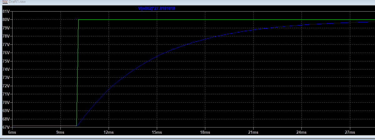
Do I need ST-link to update to the latest boot loader and firmware?
Unless you have bricked the bootloader you should be able to update it over USB, the firmware has almost made it into VESC Tool which should make updating a bit easier.
Hi TechAUmNu,
In some cases over voltage protection is not fast enough. Have been playing with 100V setup with LAB power supply which has low output capacitance and accidently pressed regeneration button, consequences - two blown FETs, one on low side, one on high side. Over voltage protection was set on 105V, FETs used 150V so in total 45V difference was not enough to protect the FETs.
I'll to will try to do some testing with this protection.
Martin.
Done some measurements with over-voltage protection and it's reaction time varies from 1ms to 2ms.
Hey e-biker,
Yeah it really isn't good enough to rely on for protecting the fets, we need reaction time in order of a few uS at most so hardware protection would be best.
That's why I decided to add TVS diodes so there is at least something that tries to protect the fets.
I have 100v fets and set max voltage to 70v, with TVS kicking in at about 72v.
If fets do get blown, its normally only 1.
Euan
Hey,
Yeah i fought about hardware protection too, but you have take some sacrifices then doing small factor ESC.
If you have enough capacitance software protection should be fine, bad things could happen than you hit regeneration on fully charged battery pack, in this case electrolytic caps should help. It's not hard to calculate the capacitance needed.
I'm thinking adding a tvs diodes to, but doesn't decided is it necessary. Those ones that you chose is pretty fast, I like them.
Had done some crazy testing today, was trying to blow some FETS. All of that is just to decide if scope is showing noise or real voltage spikes then FETS are switching. Managed to get spikes over 30V of fet nominal voltage and fets didn't blown up (FLIR not showed any heating signs to), so I'm assuming that what scope shows is just a noise. Maybe adding those tvs diodes would clear out things further.
You are so lucky if you are blowing just one fet, usually I get 2 blown fets. Will try to use faster fuses to prevent that (want no plasma balls any more).
Martin.
If you are getting lots of noise, make sure to use the little spring that goes on the end of the probe, or solder a coax directly to the board, get as close as possible to the supply and ground across the fet. When I measure I do it across the ceramic capacitors that are directly on top of the fets so the whole loop area is only a few mm including the fets.
I might add hardware protection at some point but for now doesn't seem necessary as long as you are reasonably sensible with settings.
At the moment I am working on an even smaller version for mass production, should be doing a batch of 100 in about a month. Main change is to take off a shunt per phase and the press fit terminals, so its now 2x 500uOhm. So max current measured will be 330A. Saves a lot of space removing the terminals and means the case can be better sealed with just holes for wires to pass through.
I also changed the input connections from 3x XT90 with 10AWG to 3x XT60 with 12 AWG. Which cuts down unnecessary weight quite a lot. The maximum battery input is set to 180A so the XT60 should be fine.
Wow, looks awesome, size and specs are too!! Gosh those 3D visualizations looks so great, maybe it's time to change old 2004 pcad to something newer!
I'm fixing all my bugs in driver board and planing too add a hardware protection for over-voltage if it turns out that TVS diodes can't handle it. Probably will do some testing with 100V today after parts arrive for my damaged 5kW power supply.
Yeah I had considered out terminals just because they are so beefy and there is no real benefit for using them.
Those are a TVS diodes near electrolytic caps? You used 3kW or 5kW? Ordered a few 5kW ones.
Can you tell what are approximate costs for 3D printed case and aluminum heat sink? Still haven't decided which path to go - make a more complex heat sink and cover it with a PCB (like Vesc 6) or make a simple heat sink and more complex plastic cover with 3D printer (preliminary cost 45 Euros).
Martin.
Yeah Altium 3D mode is the best :D
I have 3 of the cisco ws-cac-6000w, which do 42v @ 140A plus really good overcurrent protection.
The TVS I am using at the moment are 1.5kW through hole ones just tacked on the board as I didn't have any pads before. Those SMD ones are 3kW https://lcsc.com/product-detail/TVS_SOCAY-Elec-SMDJ64CA_C396542.html
Depends a lot on quantity, probably about 30-100usd for a machined heatsink at 1-5off. 3D printing case is pretty cheap if you get PLA or ABS about 10-15usd, mine are MJF Nylon12 which is quite pricey even at 100off. For a single part though MJF about 40usd.
Hi TechAUmNu,
Is there a 3.62 firmware file for the A200s V1.3.2?
thanks
Hello!
I just received my A200S and was happy before I accidently ruined it… ☹
I connected with the VESC tool app and it told me that communication was limited due to old FW. I updated the FW trough the app but I probably chose the wrong board or something because it’s not booting up after this.
Could you please provide a compiled FW for me? I have a SWM programmer and I am able to connect, but I don’t know how to compile a FW from github.
I think that I can fix it if you give me the correct hex file.
Br Carl
Latest firmware will always be here:
V2.1: https://github.com/vedderb/bldc/raw/master/build_all/A200S_V21/VESC_defa...
Hello, TechAUmNu!
I tried to measure resistance and inductance of motor and one MOSFET of lower phase leg (phase C) burn out. After that I changed it and saw code:
https://github.com/vedderb/bldc/blob/master/hwconf/hw_a200s_v2.h
In BOM used 0.2mOhm current shunt resistors (CSR1, CSR2, CSR3 - CSS2H-3920R-L200F). But in code resistance is noted 0.5mOhm.
Also temperature of MOSFETs measure wrong. I used resistors for potential divider like on schematics.
https://ibb.co/0Z0cHKb
https://ibb.co/HVyXgPg
What should I do to fix this problems?
Not sure what BOM you are looking at, this is the right one https://docs.google.com/spreadsheets/d/1beLjvNLt2vmFFOuJaIJZOYP_mtelpLUoSm4-4s8Qnsw/edit
Donno about the temperature, sure you put the resistors in the right place / orientation?
Been working on V2.2 for the last few months, it adds many new features and improvements to the hardware. Pictures to follow.
Question: would it make sense to add TVS protection between the source and drain of each group of high and low side mosfets?
NextGen FOC High voltage 144v/34s, 30kw (https://vesc-project.com/node/1477)
I have TVS between V Supply and Ground (high side drain -> low side source) and Phase -> ground
This is the board as I am going to be ordering them. Its a 2 layer board with 10oz copper.
I noticed you can now get 2 layer metal core boards quite cheap, so for the first set of new units I have ordered half with metal core and half normal FR4 to compare the difference.
Reading on the metal core gives me numbers about 400A for a 3oz 6mm wide track and 60A for a 0.3mm via! That is mental.
Hi TechAUmNu,
Great work! Love this.
Do you plan on making the version 2.2 opensource as well? Where can I find the files for the same?
Are you taking orders for the new version? Where can I order these boards?
Thanks
I have been running 400A at 100v while bench testing my 24F controller with one layer Al substrate 3oz used for the power stage. Plus copper strips for reinforcement. I think metal core is the **right** way to go with SMT mosfets. FR4 and high amp SMT mosfets just don't mix well together. You'll be dealing with a lot of heat issues.
NextGen FOC High voltage 144v/34s, 30kw (https://vesc-project.com/node/1477)
where did you order your cheap 2 Layer Metal Core PCB's?
I got mine from PCBWAY, they will do single layer or dual layer metal core boards with the metal on either one side and both layers stacked on top, or on either side of the metal with insulated vias going through it.
Here are some pictures,
the black board is 5oz FR4, matt black, ENIG
green board is 3oz metal core, green, HASL - You can see that I had to reduce the number of vias to stop them from shorting as they went through the metal. To give you a via, they will drill a bigger hole and insulate it, then drill again and finally plate it.
Hey Guys,
I was setting up 200A esc and had a problem. I was able to connect. Then I uploaded the appropriate firmware. After that I was able to start programming. In the FOC wizard when I ran detection, the motor made no noise and the following message was displayed: "Detection failed. Reason: Sensor detection failed." Am I missing something simple? Everything is plugged in and I've triple checked the wiring. Any help would be appreciated. Thank you.
Thom Olson
Are you getting any data under Real Time Data tab when RT button is pressed and the controller is connected? If so, check the fault code and the battery voltage it's reading.
The first thing I do with a new controller is set the voltages right. The default value are set 57v max and my battery pack is a way above that, so overvoltage fault triggers and that prevents detection from working.
NextGen FOC High voltage 144v/34s, 30kw (https://vesc-project.com/node/1477)
I am getting realtime data. The fault code says "Overcharge". The Battery voltage reading is 60v on the money. I'm using a 16s8p battery.
When I try to do the FOC wizard I get the result that I mentioned above, but when I do it under the FOC tab, the motor hums and turns a little bit. Then it returns a message saying that "R is 0. Please measure it first." I thought that it was doing that for me.
Thom Olson
You mean "Overvoltage"? Go to the General->Advanced tab and bump up the input max voltage to 61v or whatever your highest voltage is on the battery. Hit write motor configuration. You should be able to run detection after that. Just make sure Fault in the Real data tab says "None".
NextGen FOC High voltage 144v/34s, 30kw (https://vesc-project.com/node/1477)
Thank you for your help. We're making progress. The wheel spins up now, but a few seconds after that, the ESC disconnects. R and L detection works but then when it checks the lambda the problem happens. There is a message saying that the detection failed because the ESC disconnected during detection. Do you have any idea why that might be?
Thom Olson
You may need to adjust the current (amps) in the detection dialog before you attempt to detect the flux linkage. It spins the motor in open loop and sometimes need specific amps to attempt to spin the motor in open loop. I would try values between 10-30amps. Also, this is very much specific to the motor, so it would help to know what kind of motor you are running.
NextGen FOC High voltage 144v/34s, 30kw (https://vesc-project.com/node/1477)
The motor is 60v 1600w. It has is rated for 50A continuous current. I think that I understand what you are talking about above. I mess with it. Thank you again.
Thom Olson
Here is a link tyo the exact motor.
https://www.alibaba.com/product-detail/Electric-Bicycle-Motor-bicicleta-electrica-60V_60779211149.html?spm=a2756.order-detail-ta-ta-b.0.0.184b2fc2CQZNWk
I've meddled with the current and erpm. There has been some difference, but for the most part during the flux linkage part it still disconnects. During the initial detection the observer gain does not get calculated. Is it supposed to?
Thom Olson
Ok, so a generic Chinese hub motor. Should work.
I am hoping you raised it off the ground and trying to free spin it with flux linkage detection unloaded? It sounds like something is blocking it from free spinning it.
NextGen FOC High voltage 144v/34s, 30kw (https://vesc-project.com/node/1477)
I just restarted everything and suddenly it worked. I had tried this before and it didn't. I don't know exactly what happened, but it's running smoothly. Thank you.
Thom Olson
Thank you again. Does this ESC work well with BLDC? With these types of motors it gives a little more aggressive performance.
Thom Olson
Define aggressive performance. I am guessing fast acceleration from 0rpm. Is that bad or good? Most people think it's great and it's one big thing that sets EVs apart from ICE vehicles.
However, you can in fact adjust your acceleration if you like by dropping motor amps and/or changing the throttle input curve.
NextGen FOC High voltage 144v/34s, 30kw (https://vesc-project.com/node/1477)
Acceleration, top speed and braking power.. Honestly, I'm not too concerned about top speed. This motor can go far faster than I'll ever need ot go. I'll play with the amps and motor curve a bit to see what I an do about things like acceleration.
Thom Olson
Just drop the battery and motor current by 1/2 of the present settings if they feel too violent. Make sur to use FOC and Current control mode. That provide the most natural throttle response on a bike very similar to a gas bike throttle response.
Don't use duty cycle or PID speed for your application.
NextGen FOC High voltage 144v/34s, 30kw (https://vesc-project.com/node/1477)
So I got my new boards in now, but having some issues with oscillation on the gates. I took a video running in DC mode to show what happens.
DC mode holds one leg down then pulses the other high to reach the wanted current. I was slowly increasing the current each time, after about 25A it starts to get bad enough to cause big problems.
One interesting thing was doing it constantly was not a problem but leaving it for a few seconds and trying again made it much worse.
Any ideas? Thinking adding a cap on the gate might help. I already tried gate resistors about 8 ohm, 0 ohm and 1.6ohm video is with 1.6 ohm fitted.
A clear gate route layout picture would help here to confirm that's likely the issue. You can mitigate that however with higher gate resistance values. 1.6 or even 8ohm is too aggressive in most cases. You need nearly perfect gate routes with that. Try at least 10 or better 20 Ohm. Caps might work if you are lucky enough but you need to make a good guess with the value. I've tried 10nF with my design and it made it worse.
NextGen FOC High voltage 144v/34s, 30kw (https://vesc-project.com/node/1477)
Low side, with 1R6 gate resistors this looks really good and clean. No ringing at all. It is far away from the current path and perpendicular to it so should be fine.
High side, i think the problem is caused by the quite long section parallel to the current path. Capacitors were added between the pins on the connector and right at the end of the gate signal trace.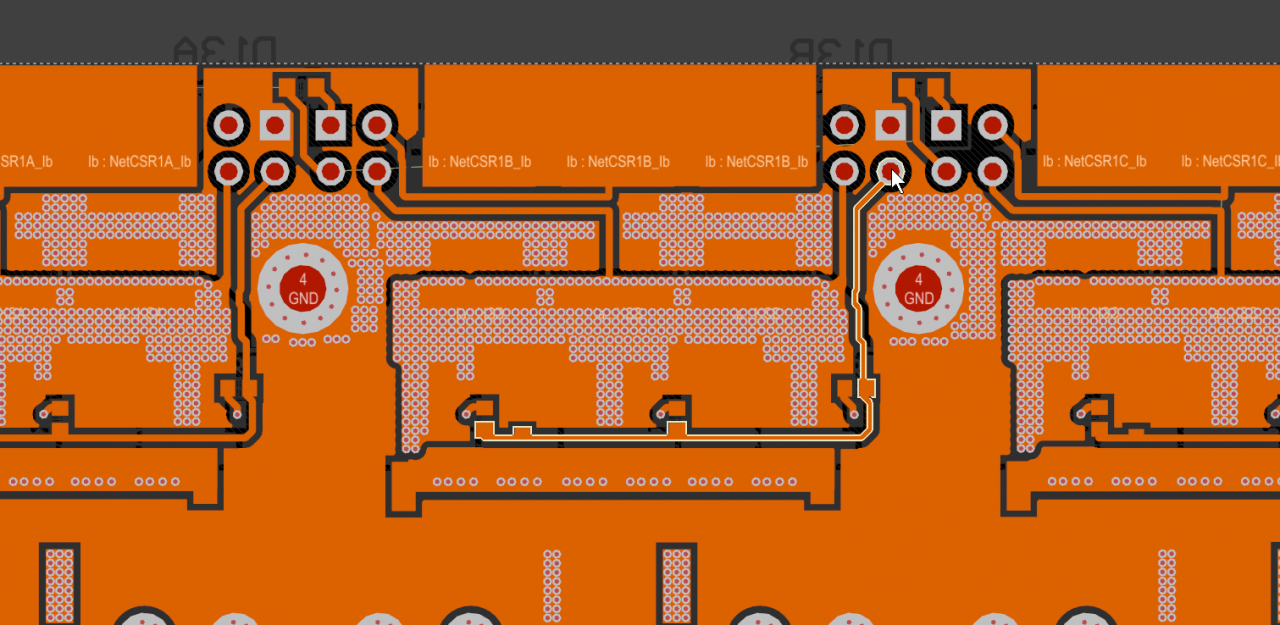
Before adding caps, spectacular ringing causing mosfets to turn on and off. Frequency of the ring is about 50MHz.
Measured using spring ground on probe.
After adding caps (2x 22nF), much better but still there, going to replace gate resistors with ferrite beads.
Measured using spring ground on probe.
Output is now clean, ringing on highside edge is caused by long probe ground lead.
That makes sense that the low side behaves much better because the gate path is super short. The high side is like 6x longer and it's wiggling between high current paths. You want them to have the same length and symmetric. The return path ideally needs to be right under the gate route and nothing under it. I know it's hard to do with two layers. I also use two resistors per side. One larger near the the gate driver and one smaller value very close to each mosfet. This is to deal with the ringing.
NextGen FOC High voltage 144v/34s, 30kw (https://vesc-project.com/node/1477)
Thank you for your help. I've done all of these things and a bit of testing. I can get the motor to roll and break on pavement, but on level dirt, I'm at a stand still. There are sounds, but I'm not going anywhere. The 60v 1600w motor with a kv around 30 should get going on level dirt. I'm either missing a vital setting or the battery isn't living up to expectations. It's a 16s8p 21 Ah battery with a 50A BMS. I'm hoping there is a simple solution to this problem. Thank you again for taking the time to help out.
Here is a link to the battery:
https://www.aliexpress.com/item/33023585618.html?spm=a2g0s.9042311.0.0.4...
Thom Olson
Post your configured settings, at least, from th Motor->General tab. It makes no sense that it runs on pavement but not on a dirt road. Have you tested it under load (with you being on the vehicle)? How is it accelerating? I thought you mentioned it was too fast for you.
That battery is shady. Be wary of stuff from Aliexpress, especially batteries, and especially when they don't name the specific cell brand and model used to make a pack. Because they don't name the brand, like Panasonic/Sanyo or Samsung, I would have to assume the worst which would be Chinese brand which can be really bad. It's unlikely to be the pack though, even if it's subpar. 8 in parallel should give you at least 20-30A which should be enough to push a bike. Check if the voltage drops when you try to accelerate and how much it drops. But most likely, it has to be something with the controller configuration.
NextGen FOC High voltage 144v/34s, 30kw (https://vesc-project.com/node/1477)
Do you know the best way to upload pics here? When I try to upload pics, it just asks for a link. I have screen clips of the motor->general settings. At the bottom I have included links to data gathered using a metr pro Bluetooth dongle that I have. The first data set is from an unloaded bench test. The second from blacktop while loaded (with me). I could not push full throttle here for safety sake. The third is from dirt while loaded. I was able to push full throttle. The motor made noise and tried to go, but couldn't.
The dirt that I am testing in s not packed dirt like a dirt road. It's a bit looser than that. I'm kind of suprised that it won't go at all. The acceleration and breaking on black-top is quite nice. When I had mentioned that it is too fast, that is speculative, based on its ratings. I was referring to the fact that FOC seems to be a bit slower in my experience with different projects, but that is not important because the motor should go far faster than I will ever want to go. Here is a a link to the project thread on esk8.news http://forum.esk8.news/t/3sk8esk8-mtn-build-begins-a-16s-battle-axe/5595. It's the first time this ESC is being used in a project on that forum.
I'm working on learning to build my own batteries at the moment. For now alibaba-express will have to do. I took off the wrap and it does look like no-name cells, but there seems to be plenty of nickle strip to handle the amps.
Here is the vesc data.
http://metr.at/r/rP0q5
http://metr.at/r/NSNNc
http://metr.at/r/V1NYY
I hope that all comes through alright.
Thom Olson
Pages