Updated 9//8/22.
Specs:
1. Three board design: Power stage, DC link/gate driving/Sensing, and control/brain board. Power stage is a single layer aluminum'/IMS board interfacing directly to the heatsink.
2. 24 150v rated mosfets in TO-Leadless package. Total voltage de-rated to 140v as a safety margin.
3. Full isolation from the power stage for reliability and safety.
5. Shuntless current sensor design with capacity to measure up to 1000A
6. Integrated Bluetooth and WiFi on board (ESP32)
7 Seamless over-the-air firmware updates
8. On Board buzzer for alarms, etc.
10. Fully enclosed aluminum heatsink providing 360 degree heat dissipation.
11. Custom Android and iOS application allowing easy setup (motor detection, throttle, etc) with integrated moving map and basic nav capability (in beta)
12. Online logging from the app directly into the cloud database with ability to monitor real time and historic data (anything from power consumption, to voltage, IMU, etc.)
13. DC Boost charging capability allowing to use any DC source with voltage lower than the battery target charge voltage.
Options:
1. Capacitive touch mini display that allows to fully configure the controller over Bluetooth and can be used as the instrument dashboard.
2. Remote connectivity package (includes on board GPS, GSM/LTE module with 3 year service included. International coverage for 70 countries). Allows to locate/track the vehicle, and send commands such as engage brake/panic mode, and anything else that makes sense - new commands will be added via updates).
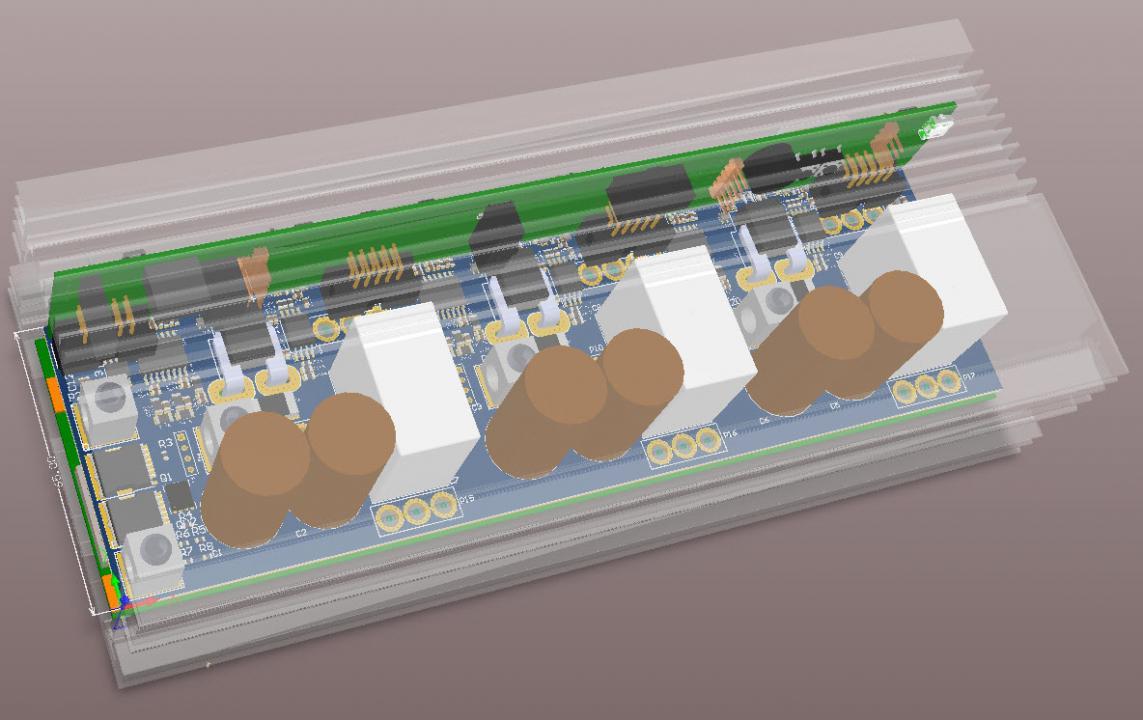
A bit outdated but mostly valid 3D model of the internals.
High level schematics
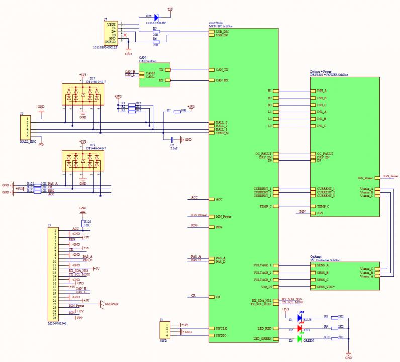
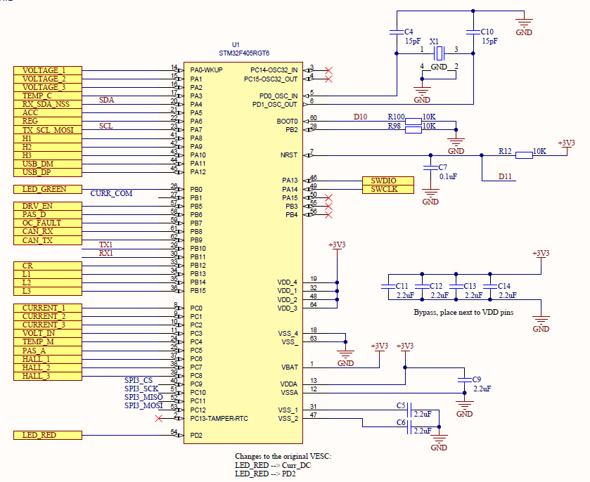
MCU
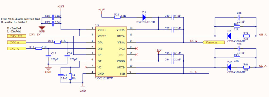
Gate drivers:
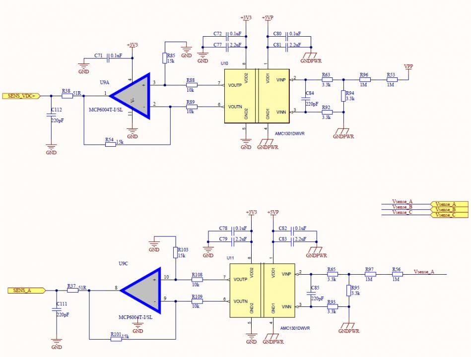
Voltage sensing for DC and Phase:
Power stage:
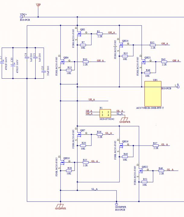
A resistor 5R6 or 6R8 should be placed between Gate drive SH_x and Half bridge mosfet midlle point.
A schottky diode (3-4A 200V rating) should be placed between Gate drive SH_x and GND, diodes anode at GND.
Bootstrap capacitors value is about 100uF. And a parallell tvs (P6KE15)
A varistor or TVS (5KP140, 150) .should be placed between motive power and GND.
Power mosfets should be placed at the bottom of PCB for easy assembling a heat-sink.
And an isolated flyback power supply (UC3842, AP8012, Viper2x, 100x, MA3810, ..etc..) should be added.
I appreciate the recommendations.
Could you elaborate a bit on what is achieved by each modification/addition? That would help a lot, not just me but other people that are working on hardware designs.
I do use a non isolated 12v power supply and run via the isolated 12->5v DC/DC but 12v for mosfets stays non isolated.
The power mosfets are surface mounted on the aluminum substrate which is mounted to a heatsink.
NextGen FOC High voltage 144v/34s, 30kw (https://vesc-project.com/node/1477)
Yeah the help is good, a few questions for the recommendations.
Why would you add a resistor there?
What is the purpose of the schottky diode?
That is an insanely large bootstrap value!
Might want a bigger TVS than that maybe 10-15kW one.
Those fets are cooled through pcb and I think he is putting it in an enclosure. So coupling the al pcb to the enclosure would be better.
Seiconductor Manufacturer's ANs are to be read on. Some lists below.
http://www.irf.com/technical-info/apphandbook.pdf
The purpose of the schottky diode and a series resistor to phase connection is to protect the driver IC from malfunction at worst case conditions. Another series schottky diode (like SS3100) to driver IC supply line should also included to protect itself. Mosfet could be broken, and this results the series resistor to broken, too but driver lives.
In some situations motor driver could emulate a boost DC-DC converter and this makes the voltage on main supply line to increase to dangareous levels. So a MOV , TVS or a dummy load breaking controller could pretend this.
Including a flyback supply could make it easy for working on, otherwise ready to use DC-DC converters (Vicor, Meanwell etc..) are ok.
Mosfet's G-S region is so sensitive, so a parallel TVS or zener and a capacitor could be added to protect mosfets. If not using the external gate capacitor, sometimes rising of motive voltage could make Mosfet instantaneously on (although it should be Off) and this could lead to a cross-conduction. This phenomenon could also lead to Vgs voltage to increase to unacceptable levels and mosfet is to be broken, so a zener also necessary here. Most malfunction of mosfets occur because of abnormal voltages.
PCB layout is also very important, for 150V supply a 5mm space between the lines are recomended. For these places, a ground or seperator copper area should not be used. Otherwise short circuit could occur in course of time because impurities in epoxy area could lead to conduct.
Stackable pcb layout is very good for seperating power pcb. It could be easily changed for repairing.
Regarding the size of the TVS on the phases to protect against spikes I am thinking that 15kw one would be an overkill even for a 20kw controller as it would not be conducting all the time but will engage only in those hopefully rare cases that should not happen in the first place. But if they do, the TVS will save mosfets.
NextGen FOC High voltage 144v/34s, 30kw (https://vesc-project.com/node/1477)
You mentioned in another thread that you have ran a QS 205 hub motor with this controller, was that just a prototype you ran with the hub motor or have you made the PCBs and ran an actual unit already? I've been looking to switch to a 100v controller but didn't want to leave the VESC platform behind
I built a dozen of prototypes before settling with the current design. All prototypes use real PCBs made at PCB factories. I have a few preorders, so I'll be running a small production batch (< 100 units) with expected deliveries in Jan and Feb.
NextGen FOC High voltage 144v/34s, 30kw (https://vesc-project.com/node/1477)
Did you make any of the changes that skyline1970 suggested?
I could not make sense of the most of the recommendations. I wish I could but I need to have a good understanding of the purpose of a change before I can make a change.
The only thing I did was adding a 5kw TVS on the DC link next to each high side mosfet group and added one from each phase to ground like you did.
NextGen FOC High voltage 144v/34s, 30kw (https://vesc-project.com/node/1477)
I have sketched out what I think he was suggesting in combination with both of our other components.
One question I had on your design is why the 10nF cap across the 2.2R gate resistor?
PS can these edit boxes be a bit bigger when writing a comment, its impossible to see what you are writing!
Thanks for visualizing it. It makes it much clearer now. Ignore my 10nf in parallel to the Ron. I meant to put it where you put your 22nf initially (actually right next to the 10k pulldown) but then read about some benefits of having it potentially there as well to improve the gate drive current so I left a placeholder there but did not populate. It also allows me to tune the resistance without touching the base resistor.
Tuning into the right gate resistance and capacitance is where the rubber meets the road. Getting those things right is what will largely define the performance of the controller.
I chose not add the capacitance to gate so far as it will further slow down switching. Maybe later, still need to fully validate the signals under different voltages and currents. It works well with 22R resistors so far. I am also using the Roff circuit which should mitigate the switching losses with higher Ron values.
As for suggestions. I am not sure about the bead on the Ron. That would further slow down the gate signal. Also, having TVS on the gates makes little sense in my case as the drivers I use already have them built in. Thoughts?
NextGen FOC High voltage 144v/34s, 30kw (https://vesc-project.com/node/1477)
I suggest keeping gate capacitance, inductance and resistance to a minimum, that can cause shoot through if you have insufficient deadtime, and excess dissipation in the body diode with too much deadtime.
Instead, use RC snubbers or drain ferrite beads to reduce switch node ringing and gate ringing. The power dissipated in the beads or snubbers will be far less than in the FETs.
IIRC some GaN FET manufacturers have good application notes on reducing noise and devices with very fast edge rates, like https://www.transphormusa.com/document/gan-fets-parallel-using-drain-fer...
Thank you. Good suggestions. I left some space for snubbers on the power stage board just in case but after some testing opted no to use them. Maybe later if some serious issues come up.
I just scoped the gate signals running unloaded motor and that's what they look like. Rise is about 4 times longer than the fall. I'll try to reduce the gate resistance and see how it responds. Once a sweet spot is found, I'll leave it there. Sounds like a good plan?
NextGen FOC High voltage 144v/34s, 30kw (https://vesc-project.com/node/1477)
The overall rise and fall.times look reasonable, but the little bit of a dip from the turn off implies you need a bit lower gate resistance so the driver can hold it at 0v better.
Deadtime looks about as optimal as it gets though.
Seems like a.decent approach.
Just a comment about the ACS773s, if your modifications involve putting a very low value resistor in parallel with them, do note the stray field cancelation of the ACS773 is pretty low bandwidth so weird things can happen at high currents (non-linearitities etc)
Agreed that I went a bit too conservative with the gate resistors keeping them on the higher end to allow testing other things without blowing mosfets. The larger resistor (22R) is close to the gate driver and then I have a smaller 2R2 very close to each mosfet leg. That's supposed to suppress ringing. My high and low side routes are not exactly symmetric, so chances are gate resistors for low and high side may need to be a bit different for best performance. ~1.5us time is a bit too slow for mosfets, they would be happier switching faster. Currently, I have stock 660ns dead time. I think that can be reduced as well. I will run more tests under loads to se how the curves change and post results.
Thanks for the note on sensors. It's been major challenge to find something isolated working above 200A without breaking the bank. Talk about designing you own sensor from scratch. Transducers, etc. are just too bulky and unstable in noisy environment. ACS773 seem to work well in conjunction with copper shunt of known and consistent gauge. This is the method recommended by the manufacturer. I've run some load tests and seen some non-linearity but it's not bad. Someone mentioned that copper would be changing resistance with temperature, however, the sensors is also copper so it would be the same temperature as the shunt. The measurements, however, are done on the flux rather than on resistivity, so I don't see any issues there. The sensors and shunts are soldered to the Al substrate board that is connected to the heatsink. Thermally speaking, I think it's a perfect scenario. All mosfets, sensors, busbars are thermally interconnected.
NextGen FOC High voltage 144v/34s, 30kw (https://vesc-project.com/node/1477)
I probably wouldn't go too hard on the dead time reduction unless you test it under heavy load, the diode recovery time will vary and same with switching characteristics but there is definitely room for improvement there.
There are a few sources of non-linearity when you do that, the sensor measures flux, so the current that goes through the copper shunt can influence it still if the stray field interferes. The difference in heatsinking of the two bits of copper can give them different resistance vs current curves, and that can lead to variable ratios and non linearity. The current paths have different lengths too, creating different AC currents, that also changes linearity with frequency.
A solution I often use is a poor quality linear magnetic field sensor and an PCB based rogowski coil, the field sensor takes care of the DC currents and tbe rogowski coil takes care of all of the AC currents. There are a few examples of doing similar things
https://www.riccardofontanini.it/projects/rogowski/pdf/6Wang.pdf
http://sci-hub.tw/10.1016/j.ohx.2019.e00057
These solutions require a bit more engineering, but can offer superior performance and a reduced cost, i would investigate these.
Thank you. Good stuff to keep in the perspective. I am sure there will be some learning curve and incremental improvements over time and I am investigating these opportunities continiously.
So far, I've tested with some moderate loads to compare the low amp and high amp VESC measurements with those made with an external calibrated shunt and it seems there is some non-linearity but it's not bad.
All power stage parts are thermally connected: bussbars, shunts, sensors, mosfets, heatsink.There should be very little temperature difference in any on these parts when running at any load. The temperature will rise and fall almost uniformly everywhere, but likely faster on the heatsink.
NextGen FOC High voltage 144v/34s, 30kw (https://vesc-project.com/node/1477)
I think overall the design is pretty solid, i think now it's down to mainly safety and reliability stuff.
At 150Vdc you should have 50mil clearance minimum for pretty much any safety standard, Im not certain but it doesn't look that much from the pics.
Resistors have a voltage rating, for 0603 (75v) resistors you need a minimum of 2 to achieve 150v, however since this controller will be likely exposed to harsh conditions (humidity/moisture, dust), it would best to have 3 0603 or 2 0805(150v).
The resistors would be the one for the bootstrap diode and your phase and battery voltage measurement dividers (there is 3 resistors but they don't share equally).
I don't think that thermistor is in the greatest place, maybe move it between phase A and B.
Your necking down your low side supply pretty tightly near your gate connections, I dont think that will be suitable for your current goals. Either consider not using a kelvin source connection.for your low side FETs or switching to a different topology - maybe have a 2L pcb that sits parallel to the plane of FET board, above your FETs that you put your drivers on, that way you can move the connector for your low side down and stick the high side one between the middle 2 FETs giving shorter gate lengths and greatly improving the track width for the ground connection.
Optoisolate your hall sensor inputs or some other digital isolator - as well as their power supply, they tend to get wrapped up in the phase wires when hub motors come loose, it would be a shame to essentially throw away the controller if your MCU gnd took 150V from a phase.
Don't use those 0.1in headers for cables or board to board interconnects, they vibrate loose VERY easily(even if glued), that's not something you want.
On your powersupply going to your hand controls, put a PTC/polyfuse on it, its chassis wiring so could easily get grounded.
I dont know how you are implementing a power switch but for crying out loud dont make it a wire from batt+ that you connect to a pin on the controller, the last thing you want is people running a 28awg wire with unfused 130vdc along their bike to a tiny little rocker switch rated for 12vdc, just shell out the extra for some diodes and a PFET or something...
Thank you. Good suggestions and I am glad you validated some of the things I've thought about.
Clearance for power traces. I put 1mm but it seems like for 3oz copper it ends up being around 1.2mm or so as the factory adds a bit more due to thicker copper layer requiring that. I'll add solid 1.3mm or so in the future iterations.
Resistors for gate drivers, boot strap. I am using 1206 everywhere with the exception of the 10k pull down on each mosfet leg where it's 603 due to room constraints. The voltage divider for voltage sensing has 2x 130k 805 in series on high voltage input.
Thermistor. You are right that moving them closer to mosfets would provide better reading and I would be concerned with this placement on a FR4 board. However, this is an Aluminum base board and I would be more interested in somewhat averaged temperature reading (the heatsink reading). Knowing that, I can properly adjust the power roll back numbers for the heatsink rather then mosfets. I am thinking 70-90 thresholds would be good. Mosfets are rated up to 175C but I've never been a fan of running anything above 100C (boiling point).
Low (and high) side gate traces. I see what you are saying and I agree there is a room for improvement here. Primarily, making them shorter and symmetric. This will definitely be a focus in the future development. I have no concern about the track width as this is 1mm width on 3oz copper, so those traces can take full 4/6A that the gate driver can deliver.
Isolation. Halls sensors as well as every part of the control circuit are powered via an isolated power supply. Then main power supply is 160v to 12v buck. 12v goes dorectly to the bootstrap with a 100mf cap on the it's way. All inputs including halls also have TVSs. I see that isolating halls further right their at the input makes sense and I'll look into that. I am actually surprised this is not done on every single controller.
Connectors. Those connectors are mostly for the 3D model. I am now using JST-Xh connectors that lock in place. I do use 4 pin header connector for control to power board connection that I've had some concerns about. Male SMD on the power stage might be brittle with the control board plugging into it. If the controller is dropped hard, the control board can dislocate and brake the solder joint. However, I am assembling a few controllers at the moment and reevaluating this. I've added an additional capacitor bank board that mounts on the other side from the mosfet and it can be used as a support for the control board. I am also considering some design changes that will add support for the control board on the sides.
Fusing. I am using a polyfuse from 150v to the power supply that outputs 12v. I see a benefit of adding another fuse on 12v line. As noted earlier. 12v to 5v goes through an isolated buck. I don't expect any non-isolated and/or high voltage on any controls.
Power switch. It's probably over engineered as is even though I've simiplified it recently to reduce cost. I used to have two independed power supplies: 1) 150v -> 12v -> isolated 12v to 5v -> 3.3v 2) 150v -> isolated 5 to 5v -> 3.3v. The reason I wanted to have the second supply is to have the constant on Bluetooth to enable keyless on switch but low stand by consumption. Finally, I eliminated the second supply and power the BT from the main supply. There are two solid state isolated relays: one can turn off part of the 12v supply (to disable mosfets for safety) and turn off main power (150v) to the control board. BT can control both relays, so features like auto off on timeout can be easily implemented. I am also considering adding a couple of mosfets in parallel to be used as the main supply switch to deal with connector arcing and disconnect when a fault is detected.
NextGen FOC High voltage 144v/34s, 30kw (https://vesc-project.com/node/1477)
It's not specifically the gate traces though, look at the ground connection from your caps, it gets VERY thin because the gate traces and the pad from the current sensor encroaches on it, during operation these areas will be the main areas of high current because of the low impedance source (the caps).
The reason why I say move it closer to the MOSFETs is because even though aluminium is far more thermally conductive than FR4, there is still a time constant, just like there is in the package from die to leadframe to board. Even if you lower your threshold temperature you can't really change the time constant, so to the sensor, what is the difference between a heatsoaked heatsink at 70 degrees and a mosfet that's at 175 degrees and a thermistor that hasn't heated up yet? I understand that is an extreme case but it helps illustrate the problem.
The reason i say put a polyfuse or the like on a connection to the controls is you want your controller always to be operating in a predictable state; If the wiring to the user controls becomes damaged while riding there is potential for things like brownouts to the MCU and gate drivers etc if that is where the supplies are derived, this can cause all sorts of issues and unintended operation, fusing this allows to an extent the controls to stop being functional but the controller to still function as intended, allowing the vehicle to just coast or whatever. For most of these applications, a polyfuse may not be the best option, but it is the simplest and close to the cheapest, you could also use somethingn like AOZ1360AIL with the minimum current set as a slightly better option.
For Isolated Power supplies, this sounds super dodgy, but i HIGHLY recommend phone chargers from reputable brands - most universal input phone chargers work down to 40-50V, they are made to reinforced isolation standards rather than basic isolation, often they are much cheaper than isolated DC-DC modules and they are significantly more efficient - especially at low load as this is often mandated by local regulations. For example, the lowest standby power consumption from a 150-12v isolated module is around 3.5mA, which at 150v is about half a watt (i've searched high and low, as part of my work, and even if you do find one they are VERY expensive), where as phone chargers are around 20mW and can be had for near single digit dollars.
I know about the ground traces and I had to do that due to the size constraints. I am fitting this into a specific heatsink enclosure. It's 3oz copper though and it's dissipating heat pretty well on the substrate. But I'll add some reinforcement likely in the next iteration.
I see your point about the thermistor. Will move it. Same with the control protections.
For power supply isolation, I just need 200-300mA to run the control board, so I am using 1-2W isolators. I do have a non-isolated 5v DC for phone charging and it's fused at 2A. I've used phone chargers as power supplies in the past and I think they are great to power accessories (lights, etc.) The only issues is that, like you mention they don't run at lower voltages. If used to power the controller, that would mean limiting the input range at 50v or so on the low end.
Great suggestions. Thank you.
NextGen FOC High voltage 144v/34s, 30kw (https://vesc-project.com/node/1477)
Hi, what is status of the project? I am interested to buy VESC with FOC control at ~ 120V 300A or 75V 500A.
We are running the first production batch of controllers with deliveries of preorders in early February.
Preorders can be placed here: http://powervelocity.com/home/60-18f-ebike-sinewavesilent-controller-android-ios-bluetooth-programmable-8kw.html
NextGen FOC High voltage 144v/34s, 30kw (https://vesc-project.com/node/1477)
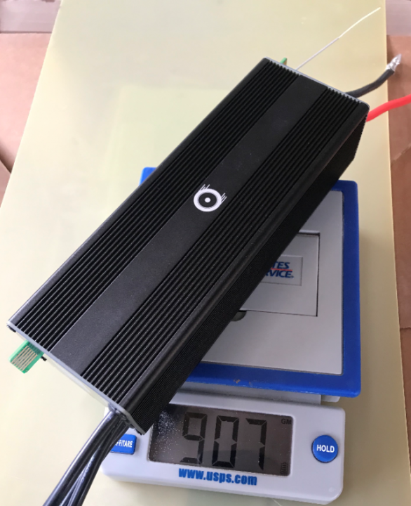
The first production batch of pre-orders is made and getting ready to be shipped to the patiently waiting customers!
The total weight of the controller is almost exactly 1Kg with 0.6kg being the heatsink and the silicon wires + lug terminals. So, the controller itself is only 0.4kg.
As we ramp up the production and gain effeciencies, pre-orders will be shipped faster.
NextGen FOC High voltage 144v/34s, 30kw (https://vesc-project.com/node/1477)
Could you provide more details about ports on the PCB? BlueTooth module?
CAN, throttle in, brake/regen in, cruise control, additional ports that can be used for anything. Bluetooth is NRF52840.
NextGen FOC High voltage 144v/34s, 30kw (https://vesc-project.com/node/1477)
I need more photos. Ports JST 2.0 PH? Pinouts? Main connectors?
I am running QS205 here : https://www.youtube.com/watch?v=KjFB1FSgx28 and from pilot https://www.youtube.com/watch?v=VoQW-HpxA_A
75/300 a bit not enough for double seater paraglider. Looking for more powerful controller. Please contact me, I left a message to contacts http://powervelocity.com
Where can i buy this controller ?
Gr
Got one more question about the controller..Would it be possible to add field weakening , found a thread on endless sphere someone got it working by editing software code. And if i use 20s battery will continuous batt amp go up ..?
Gr
Can be preordered here: http://powervelocity.com/home/60-18f-ebike-sinewavesilent-controller-android-ios-bluetooth-programmable-8kw.html
Field weakening will be added via software update a bit later.
Continuous discharge rate is mostly a battery limitation. How much is your battery rated for?
NextGen FOC High voltage 144v/34s, 30kw (https://vesc-project.com/node/1477)
To be honest I haven't built the Battery yet . I'm doing as much research as i can now . Battery i'm planning would be 22s 130Ah battery , at 3C i't would be capable of 390amp or 5C 600amp short burst's.. The motor i have chosen is QS Motors 138 70h 3000w rated I'ts usually paired up with VOTOL em150s sine wave controller .People are pushing it to 20KW plus without any issues .
http://www.cnqsmotor.com/en/article_read/QSMOTOR%203000W%205000W%20138%2070H%20electric%20motorbike%20mid%20drive%20motor%20for%20electric%20motorcycle/612.html
Gr
That motor can do 200 battery amps max in short burst before overheating. I have it on my motorcycle. 390 or 600A will likely melt it. Votol 150 is a nice controller but sinusoidal, not a FOC.
The throttle response not as good as it can be.
NextGen FOC High voltage 144v/34s, 30kw (https://vesc-project.com/node/1477)
Is that running the motor at max operating voltage 130-150v for the controller., when it overheats .? Motor it self is rated for 72v but few pwope are running it at 96v or 106v..
I would maybe feed it 40amp to 100amp max at 130v.
Gr
The power rollback feature does not limit the voltage on overheating. It limits the current. However, chances are it will never overheat running up 100A. It's designed to take more.
NextGen FOC High voltage 144v/34s, 30kw (https://vesc-project.com/node/1477)
It looks very good, can you share pics assembled pcbs ?did you use heavy copper? have you tried 600A, and how long can it last?
do you have videos of youtube of this controller running larger motors?
anthony miller
Could you share video of motor acceleration with relatively low and high currents, like 3 and 300A ?
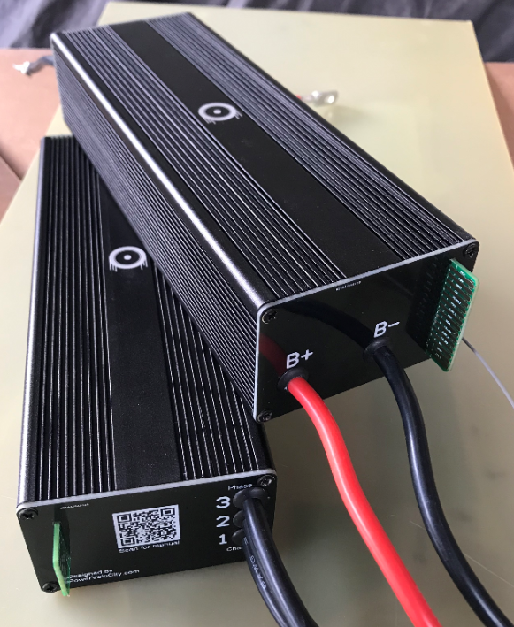
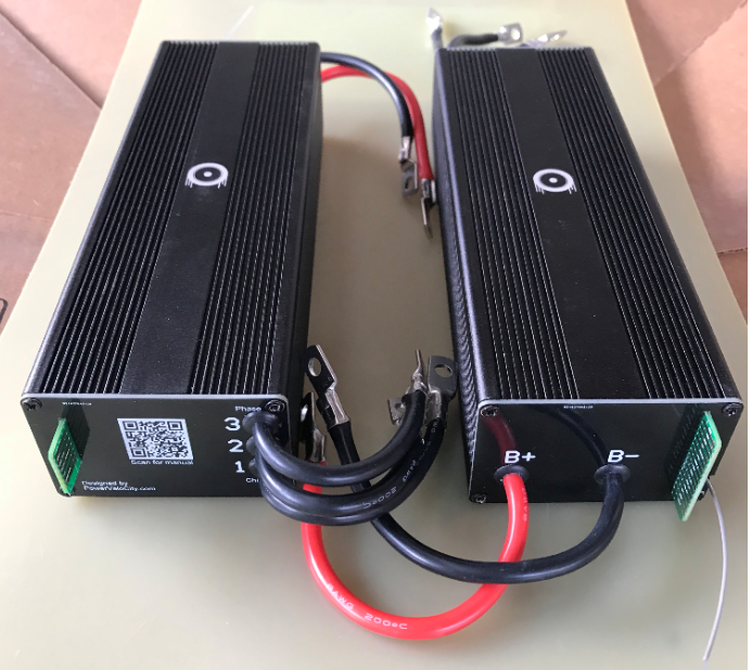
Here are some pictures.
Hi amp traces are reinforced with copper. I haven't tried 600A just yet, don't have a load to test it at those amps. But tried 150A batt, 300A phase on a bike. Works fine. Temperature goes up to 40-45C max.
NextGen FOC High voltage 144v/34s, 30kw (https://vesc-project.com/node/1477)
This is running a large inrunner (~10kw). You can skip to 7:00 to see the motor run:
NextGen FOC High voltage 144v/34s, 30kw (https://vesc-project.com/node/1477)
Cool, can you share more info about your experience with aluminum pcb, pros /cons vs standard pcb.Is it hard to solder components?thanks
Pros are obviously great heat absorption/dissipation, strong construction, automated assembly possible due to all parts being SMT, easy to interface with the heatsink.
The biggest con is almost impossible to hand solder anything on it due to one if its pros (great heat absorption/dissipation capability) which is not a big deal when everything is wave soldered.
Another thing is thicker copper is way too expensive on Al substrate compared to FR4 but it looks like that is going to change pretty soon. For now, I am just using copper buss bars which works but that also costs extra parts and time.
NextGen FOC High voltage 144v/34s, 30kw (https://vesc-project.com/node/1477)
Nice work!
But isn't your FET's to far away from the capacitors? At higher voltages and currents there could be a problem with voltage spikes when using lower inductance motors.
I'm switiching back from AI substrate to FR4 board for my next design as there is no easy wayt to trace a capacitos near fets for best DC filtering.
For soldering on AI substrate use plumbum solder, it helped for me a lot of times.
Martin.
Caps are very close (within a few mm) to the high side mosfets but farther (a few cm) from the negative rail. I am planning to reinforce the negative to caps connection with copper in future versions.
NextGen FOC High voltage 144v/34s, 30kw (https://vesc-project.com/node/1477)
I see customization message possible on preorder page.
What customizations available?
Do you have approximate batches schedule?
Please publish connectors pinouts.
That's just an option for other products. No specific customization is available for this controller at the moment but there will be options you can add to it eventually.
Will add manuals, pinouts to the product page.
NextGen FOC High voltage 144v/34s, 30kw (https://vesc-project.com/node/1477)
Hello Vadicus,
Today I tried to preorder, but it is impossible now: 'There are not enough products in stock'.
Is it possible to preorder?
Sold out :) We decided to slow down just a bit pending testing for various applications. But planning to re-open preorders later this month.
NextGen FOC High voltage 144v/34s, 30kw (https://vesc-project.com/node/1477)
Please build some before May..
Yes, likely, much sooner.
NextGen FOC High voltage 144v/34s, 30kw (https://vesc-project.com/node/1477)
Pages