So I'm trying to get FOC to play nice and realized that the autodetected motordata changes a lot with different input voltages etc.
On 4.12 @20V I get:
- 30.6mOhm
- 41.40 uH
- 21.388mWb
- 2.19 O.G
A200S V2 @62V:
- 29.6mOhm
- 50.96uH
- 23.293mWb
- 1.84 O.G
So not that far off since it's on different hardware. But when i do my own measurements we see values far off the "autodetected" ones:
- 83mOhm (calculated average from voltage drop @ 1,2 & 3A)
- 194uH average @1kHz (DE-5000 LCR meter)
- ?? mWb
- ?? O.G
So what should I use? The suggested values gives me a rough ride at higher currents. How do I calculate mWb and observer gain?
Your inductance measurement will be off for a couple of reasons, the first is, the VESC measured inductance and resistance is that of only one coil, so if you use an LCR Meter you will get a number twice as high minimum because in a Y configured motor you're measuring two phases in series. That would still put your inductance quite a bit below measured values and your resistance reasonably close. This makes sense. The test current of the motor controller for inductance measurement is far higher than an LCR meter so this saturates all of the small parasitic inductances dropping them to 0 leaving you with only the real inductance. If you use an oscilloscope, large cap bank, MOSFET, diode and a shunt and measure the slope of the current ramp and do V=L di/dt you will get a number much closer to 2x the VESC measurement.
As for what numbers to use, I would use the 4.12 numbers, at a lower voltage there will be less error in measuring the inductance because the current ramp will be shallower meaning bandwidth and timing is less of an issue.
Yes I've noticed that the measure inductance can vary a fair bit depending on supply voltage.
bgdwiepp: Off course.. I didn't use my head
I tried 4.12 numbers on only 5s (15s normally) and FOC was really smooth??
10s got a bit rough and 15s almost got me worried.
I used 85A motor current and got spikes up to about 85 so I figure that's no problem?
It's pouring outside today so I can only test inside today.
What is your PWM frequency at? If its less than 30khz I would increase it to that. If you increase your ki a little bit it should help smooth things out too
I have similar problem, resistance is ok but inductance is 2x than 4.12 hardware.
My measurement on 4.12 is 7 uH , on my custom board is 13 uH .
Can anyone explain what can affect the measurement?
With an inductance that low, input voltage, switching frequency and dead time compensation will play a large role. If you can measure the dead time of your FETs drive and put that specific value in it will give you a much better result.
If the dead time is too low it may report the inductance being higher than it is and if the dead time is too high it may report the inductance lower than it is.
30kHz yes.
Mounted my old 4.12 now and FOC on 10s is butter smooth @120A phase/battery
I'm starting to wonder if my A200S is somewhat defective BLDC is really rough too
I just noticed that deadtime is the same for both esc, can that really be correct?
Deadtime compensation on the A200S should be 0.2uS, this is what is programed into it when I test them. You can also try 0.3uS
Ok, so I have just done some testing with a NeuMotor 8025 at 20V and 30V. I will do some testing at a higher voltage at the weekend. My findings so far are:
Changing from 30KHz with Sample in V0 and V7 enabled to 60KHz with it disabled makes startup much smoother. (MAKE SURE YOU TURN OFF SAMPLE V0 and V7 FIRST BEFORE INCREASING FREQUENCY OR YOU WILL BRICK THE UNIT)
Changing from 0.08uS deadtime compensation to between 0.220uS and 0.250uS gives the best startup, the higher values worked better when at low current and no load in current mode. The slightly lower values worked better with duty cycle mode and a load.
The inductance and resistance both change linearly with increasing voltage. Changing the values slightly doesn't seem to make too much difference. R 8.85 to 8.15, L 8.79 to 9.57.
in my case, changing values means a lot,especially when using high currents 150A and more.Usually resistance value is ok, but inductance needs to be tweaked.
I don't have problems with motor startup, only ABS_overcurrent(when starting very fast).
i would like to know more about this, if someone knows, please share.
Thanks
Reviving this old thread as I bumped into exactly the same scenario with my high voltage, high current design that's posted here: https://vesc-project.com/node/1477
I tested three motors (two hubs and one large inrunner) and all pass detection fine. They run fine after detection on unloaded motors and only if I slowly advance the throttle.
If I twitch the throttle, the motors attempt to accelerate fast but cog/stutter and/or seemingly go out of sync. This also also frequently triggers ABS Current fault. That's even with unloaded motors.
Under load, they would "give up" even if I attempt to accelerate gradually.
The issues is mitigated with lowering the inductance value by as much as 50% and/or reducing the Gain to as low as 0.1. I thought there was something specific to my hardware that I needed to adjust for but after reading this thread, I am not sure. One another detail is that I run detection and the controller above 100v if that makes any material difference.
Thoughts?
NextGen FOC High voltage 144v/34s, 30kw (https://vesc-project.com/node/1477)
Had same problems, after changing Motor flux linkage slightly it worked much better, see my thread https://vesc-project.com/node/922
Link to forum post: VESC help offered for private persons and companies
Website: www.electricfox.de
Yes, thank you for confirming this. I've just played with more settings for the last couple days and found that reducing the flux linkage helps mitigating cogging/out-of-sync/ABS overcurrent issues.
So, to sum it up, there are three values that affect this:
1. Inductance. For me, I have to drop it by 2 to almost eliminate cogging. I may still be getting ABS overcurrent fault if I twitch the throttle.
2. Observer gain. If I detect with the stock VESC code, for my motors (large heavy hubs and inrunners), I get detected values of around 1.0-1.22. Get a lot of cogging and ABS faults with that. I have to drop it to almost 0.1 to mitigate the issues.
3. Flux linkage. My detected values hover around 30-35. By dropping it to 25-28, I eliminate the ABS overcurrent issues.
One thing to not is that dropping the inductance or flux linkage too low creates another type of noise. Kind of out of sync but different sound.
My strategy around making it work for now is to slash the inductance by half and drooping the linkage by 1.2-1.4.
I wonder how this will change with higher voltage like 140v. But I am yet to built that kind of a battery.
NextGen FOC High voltage 144v/34s, 30kw (https://vesc-project.com/node/1477)
Thanks for the writeup of this should help a lot for all of us making high power controllers. Would be good to have a toggle we can enable in firmware to change default detection values to be closer to this.
I certainly think that having a lower inductance value set will be safer.
Have you tried detecting at lower voltages and graphed the detected values? Would be interesting to see what is changing.
I tested with 52v and 95v battery voltage and the resistance was about the same, just a 2.4mOhm more with higher voltage.
The inductance was about 34mH less with higher voltage. The flux linkage was the same. I tried to run higher voltage with the values that were detected at lower voltage and unloaded motor was oscillating at highest RPMs. Currents were jumping up and down. Then I applied the values detected at the high voltage and it was working fine after that.
In my case, I just modified the code to derive the values that work the best.
NextGen FOC High voltage 144v/34s, 30kw (https://vesc-project.com/node/1477)
What code did you change? Do you have a github of changes I could have a glance at?
This function is responsible for inductance calculations in FOC: https://github.com/vedderb/bldc/blob/210ec40d746236264fc9ec6bd95384d1714...
You can tweak the value it returns. For example, "/ 2" at the end of the Return would half the inductance value when you run detection: return ((avg_voltage * t) / avg_current) * 1e6 * (2.0 / 3.0) / 2 ;
NextGen FOC High voltage 144v/34s, 30kw (https://vesc-project.com/node/1477)
Not sure if this would be the right thread to post (it is quite old)...
It occurred to me that the measured resistance of the exact same motor on two different VESC controllers were very different: VESC 6 MK V measured 15.5 mOhm, whereas the VESC 75/300 measured 24.99 mOhm. The setup is exactly the same (just swapping the VESC controller). Although the firmware is for different hardware off course, they are both version 5.2. I assume the code responsible for measurement is the same, so the only thing left is really the hardware then I suppose. But I think a difference of almost a factor 2/3 is a bit suspicious, any ideas? I measured the windings offline using a DC current supply, and the line-to-line resistance measured on all pairs were close to 31.58 mOhm, so the calculated value for the stator resistance (per phase) by VESC 6 MK V is close to what I would expect.
I'm observing something similar. On a Raiden 7, FSESC 4.20, and Phaserunner and a 9C ebike hub motor I get ~75 mOhm, 75 uH, 25 mWb for detection values and excellent FOC performance. On an FSESC 7550, I get about 150 mOhm, 120 uH, and 15 mWb and severe cogging and lurching under load.
Using the previous good values in the 7550 does not result in smooth FOC performance.
Does anyone have suggestions for a manual tuning strategy for the 7550?
Before doing the detection, try to drop to switching frequency to 5-10kHz. Once detection is completed, you can put the frequency back to its normal value. See if it helps to produce more consistent detection values.
NextGen FOC High voltage 144v/34s, 30kw (https://vesc-project.com/node/1477)
This is for the FSESC 7550 and a 9C motor. The resistance was fairly constant (133 mOhm at 5kHz and 147 mOhm at 50 kHz). The inductance had more variation as seen below (8 samples at each frequency). The values at 50 kHz matched the previous values best, but detection and operation at 50 kHz did not give a good tune.
Detection at 5 kHz and operation at 50 kHz gave the best (but not yet good) tune so far, so thank you. Any advice for making my random walk through the 6-D space (R, L, lambda, KI, KP, Gain) a little more efficient? Can I look for certain features in the real time or triggered data?
I saw above that you dropped inductance and linkage. When you dropped the inductance, did you use vesc tool to recalculate the KI and KP?
I would say at lower frequencies, you are likely to get more accurate measurements with less than perfect hardware which seems to be the case here. As discussed earlier, the resistance and inductance measurements will vary a lot depending on the input voltage if you run detection at higher frequencies like 10khz and above. at 5kHz, I was able to produce more or less consistent results at different voltage.
I would also verify the current sensor measurements are calibrated well. You can run a 10-50A in DC mode and measure the current with an amp meter and compare to what VESC is reading. It needs to have correct gain setting to start with before attempting to tweak anything.
Other parameters you can try is the gain and flux. Lowering the gain does help reduce overcurrent event most of the time. Same thing with the flux. You can try to drop it 1.00 at a time and see if that helps.
Some people had success doubling or halving the KP and Ki values. You try that last after you tried the above. I didn't have much success with that.
NextGen FOC High voltage 144v/34s, 30kw (https://vesc-project.com/node/1477)
I wasn't able to tune any further because I had a catastrophic mosfet failure that burned entirely through the PCB. I'm unable to upload a photo now but will try again later.
Anybody know of a problem that might explain both the detection problems and mosfet failure? It seems they could be related.
The motor current was limited to 60 amps in VESC tool which I assume is below the mosfet failure range. My naive hypothesis is a shoot through event, but the board uses a driver (UCC27211) that should prevent it.
Can be a variety of reasons, but statistically speaking, mosfets are often killed by voltage spikes. So, current is less of a factor in most cases.
NextGen FOC High voltage 144v/34s, 30kw (https://vesc-project.com/node/1477)
Here's a photo of the failure area. One of the shunt resistors detached from the PCB and you can see the wood showing through the PCB.
Does this look more consistent with overvoltage or overcurrent events or is that difficult to say?
The dislodged shunt resistor is a collateral damage, not the culprit. It desoldered because the heat created by the failed mosfet.
When a mosfet fails (very often due to a voltage spike exceeding the rated voltage), it fails shorted most of the time. Sometimes, you hear a loud bang with sparks/plasma/fire. The heated particles from the mosfet and/or other components atomize creating a conductive sooth that can further short things. The PCB material may also turn to carbon and become conductive shorting other things. It's a lot of fun to watch it albeit expensive fun.
NextGen FOC High voltage 144v/34s, 30kw (https://vesc-project.com/node/1477)
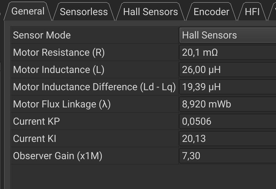
@vadicus, I have a relative big 5.6 kgs 12 inches wheel hub motor, that was shaking and getting VESC fault warnings, at high currents / high load only, when using the autodetection values. I did follow your strategy and now at motor startup it produces a lit less noise as also no more issues!! I am using the VESC Makerbase 75200 Alu. Thank you.
Auto detected values on VESC tool:
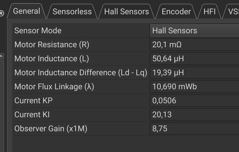
Working well with values changed using your strategy:
While your phase resistance value seems reasonable (still on the low side but really depends on the windings), the inductance does seem to be a bit low. I mean still possible if the copper fill is low on that motor but not typical for a larger hub motor. What I would do, before you try detection, set the frequency to 3kHz and then run the detection. After the detection is complete, set it back to 20-35kHz. For a larger motor, you would also want to use ~50A phase current for R, L and flux detections to better results.
NextGen FOC High voltage 144v/34s, 30kw (https://vesc-project.com/node/1477)