Hi!
I'm back with second generation of my BESC controller. I took a few different approaches this time.

This monstrosity is a 24 FET design. It uses 135V TO-220 mosfets and is designed for input voltages up to 100V. It's primary use case are light electric vehicles and bikes. It features integrated high efficiency 12V 5A dcdc power supply and custom input connectors to ensure easy throttle connection. Because of high voltage it doesn't use phase shunts but rather three low side 0.2 mOhm shunts. It was designed up to 400A phase current but we'll see about that. PCB is standard thickness 4 layer board. Busbars soldered on bottom and top carry high current. Board is also ready for high voltage modification. With suitable capacitors and mosfets it is possible to turn this board into higher voltage / lower current controller up to 150V input voltage.
To sum it up:
- 20S LiPo safe
- 400 A phase current
- 12V 5A integrated dcdc
- Easy throttle connection
- 250€ BOM from Mouser/Farnell
Project is of course open hardware and can be found in my github repository: https://github.com/galpavlin/BESC-G2
You can find pdf of schematic, 3d step files and BOM in documentation folder. Gerbers are also available.
I ordered PCBs few days ago. I'l have a few extra. If you'd like to have one write me a PM. I'll be assembling the first unit sometime next week.
Very nice ! Please keep posting about your progress on this project. I might be interested in a 150V 100Amp continuous version (using 200V Mosfet).
Hopefully the current and bemf signal will be clean enough..
hi, i'm very interested to test this version of you BESC. i'm making an electric bike with 3 25kw motors but I still doubt whether I should build a motor controller myself or buy one. i already started to design my own VESC with your BESC as an reference and inspiration. i want to run the motors on 100 to 130 volt and there are not very much esc's that can do this. so i'm curious if you already tested this version of your design. also i can not open the BOM, is there an excel version available?
I was fascinated by your results and effort in your first version. I wanted to base my own ESC on your files. I found two bugs/issues:
- both the UVW voltages and the Hall Sensors do not have any input filtering/anti-aliasing filters. is this on purpose?
- due to some bug in KiCAD the hidden pin on your SN74LVC1G04 is directly connected to GND --> GND and GNDD are connected together. i think this messes up your well thought out ground concept.
Keep up the good work!
One should be able to open .ods file with excel. If it doesn't work try installing openoffice and open it with that.
I haven't had time to solder it yet. There are quite some bugs as it's expected for first version. I'll get rid of SN74LVC1G04 since it can be easily replaced by inverting signal in software. Current sense is filtered. Components are placed in mcu sheet. I'll move them to powr stage for clarity. If I remember correctly benjamin said voltage sense filtering did not yield good results so it wasn't implemented.
I think the new VESC6 and 75/300 have switchable filters now.
I tested the controller with a small motor on 10S. The current sensors are reversed by accident but it is solved with a "-" in software.
Results look promising.
I would love to build one of these! I'm very intimidated by the software setting you have to tweak to get this thing to work through. Do you have to recompile VESC firmware to get it to work with new gate drivers and FETs? Sorry, I really don't know anything about the inner workings of the VESC or electronics in general but I know I could put one of them together. I have read so many posts about controllers like this and it seems like you have to modify the MOSFET deadtime value in the GUI but I'm not sure. What are the recommended settings and do you think it's safe to try this out with FOC on a large hub motor?
Any updates on your project? Are you are actually using the bidirectional INA240 20V/V current sense amp with the output referenced to 3.3V/2? Any reason for using this scheme since the shunts are in the low side legs of the phases? With 400A peak through a 100uOhm shunt you'll only see (3.3/2)+400*0.0001*20 = 1.65-2.45V peak output swing, which is a resolution of (2.45-1.65)/400=2mV/A. You could reference the output at 0V and use the 50V/V part to get a 400*0.0001*50 = 0-2V peak output swing and a resolution of 5mV/A.
The RMS power dissipation in the shunts at 400A peak will be close to 0.0001*(400*0.707)^2=8W for the pair or 4W each. Pretty low for such high currents. You could increase the shunt value to 150u to get an even better 0-3V output swing and 7.5mV/A resolution but with 12W dissipation in the pair.
hi!
I have built your design two days ago. Firstly, i would like to thank you for this thread.
But Unfortnately, it didn't work. I upload your gerbers and if there was no problem on them.
The current situation is , i uploaded a bootloader but the LTC7801 part is not working at 48 volts.
Does anyone have an idea about it ?
by the way i just shorted the j15 and connect +48v and ground
I made a blog page about controller. You can find information how to build it and use it here:
http://pavlin.si/besc/besc-g2/
wow, you kick youself when you go on someones design ideas.. But not really understand why they where doing it until deep diving (Aka ordering PCB's of your own design) To realize that the logic 74 IC is there jsut to invert the enable gate signal beacuse you didn't want to modify the firmware :D Pretty hilarious. Also pretty stupid of me to incorporate this into my design. BUT! I had a sneaking suspision that it might not be needed in my other designs that use different gate drivers . So I added a bypass jumper under the 74 IC.
Thanks for your designs Galp. it be nice if you connected back on your V1 foum and also sent me a PM to connect so I can show you my design ideas.
Mo
galp,
Very interesting project! Let me ask you couple of questions.
I like your fet mounting idea, good for heat sinks but, how did you manage to push bottom fets to the heat sink ?
Can you share the firmware source code ? On your web page you wrote: "Source code can be found on my Github repository." but there is no source code.
Thanks
To galp,
Straight forward approach radius quale torque it's meaning motor radius should NOT be less than radius of wheel.
And yes interesting approach to feed VOLTAGE not Current . I tested fet drivers they survived 1kV impulse Dead Time on driver 30nS on Low and High sides.
I see bottle neck in step down converter (fiscal mass on board, heat, excessive parts and electric noise) why just have separate PS for logic from stock of cells let's say
10V to 12V just will coast of 2 wires , + and common GND. I did it my designs. , But Im not good in MCU and programming is not my kick, I steal can't figured out why VESC 6 not populated on USB COM PORT??? UART , SWD working but no USB , what ??? is other options to connect to PC and VESC-Tool with out it is all dead... Windows 10 .,7 and XP with same "" UNIDENTIFIABLE OBJECT "" ( UFO) Is there any suggestions ??
Thanks to every one who is sharing knowledge.!
How can we get a few of these bad boys?
I've got some haters thinking I can't make this float https://www.instagram.com/p/CExpA8JHBrm/
Sourced 72V motor and 20s battery but no VESC.
We have 75/200 16s prototype ready, looking to push motors up to 120v.
Thanks, Aaron
To arosenthal
From my experience on open market nothing exist to be available yet. Hopefully Benjamin will help to create one.
To my previous post
Symptoms - logic PS on 1 sec boots to blinking red led an green led steady USB not recognizing in WIN "UFO"
Tried to change MCU - no effect same banana, digged in Data sheets - in boot time nothing tied to ISP or UASRT than checked 'resonator' CSTCE8M00G52-R0 its unit with present capacitors by 10pF and 40 Ohm ESR --- the resonator is not locked in 8 MHz --- it swings from 7 MHz976 to 8 Mhz every 2 seconds. I ges this is the problem ...?
If any one experienced similar situation pleas post info.
Thanks
The newly assembled BESC G2 , shows UNBALANCED_CURRENT fault with default configuration even without connecting motor.
however the sampled current waveform seems to indicate normal current curves well within 1amps and the multimeter values at the isense pins on the stm32 reads default 1.666v on all three pins.
The fault disappears and functions properly if I enable high current sensing using all three phases from FOC>Advanced options.
What could be the issue?
GL
To galp,
Found out that instead of negative (-) 20 gain in the hw_bescg2.h file we can use "INVERTED_SHUNT_POLARITY" that can fix the issue.
#define INVERTED_SHUNT_POLARITY
#ifndef CURRENT_AMP_GAIN
#define CURRENT_AMP_GAIN        20.0
#endif
Can you confirm.?
GL
gowrav, thanks for posting your code. I have a question though, when you use this code:
Did you still have the logic inverter, U7 on the board? In my case i was planning on removing U7 and physically bridging the signal between pin 2 and 4 - as Galp suggested on his blog:
http://pavlin.si/besc/besc-g2/
So I'm just wondering if I remove U7, would I still use your variant of the code?
thanks for your help.
I have removed U7 as suggested and have shorted pin 2 and 4 ,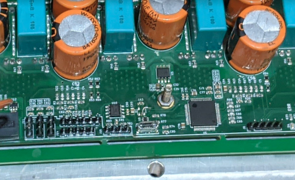
The code change basically points to how the Shunts are connected to the OPAMPS., the U7 functionality on the other hand is related to disabling PWM signals to the MOSFETS, they are not related AFAIK.
GL
Okay great - sorry for the confusion.
I finished soldering my G2 and i'm trying to connect it over usb. The flashing over ST-LinkV2 was fine. Blue LED is always on. Green LED is always on. Red LED is flashing. I installed the stm32102 drivers on win10 64bit. When i try to connect the vesc via usb the device manager shows Unknown USB Device (Failed to read device description). Anybody who had this problem before?
julwaech,
I think I'm having similar issues. I had a couple boards assembled at PCBway, so the only parts are on one of them are just the SMD parts (and U11, the 5v regulator). I used this to check if I could flash the board. I'm able to get both green and red LEDs to blink using a separate program for the firmware, but when I use code compiled from Galp's repository red and green just flash briefly about every second. In my case green does not stay on. Also, I have not been able to get the USB recognize the board. When I look at the code it seems like they are using virtual com port drivers on the STM32 and for macs, those are normally recognized with the native operating system. I also tried it on windows 10 and the com port did not come up in the device manager.
I'll try installing another more simple virtual com programs on the G2 and see if I can get it to communicate. I'l report back if I make any progress.
I have gotten success to get the G2 to connect to VESC-tool.
Galp posted a binary file on his blog:
http://pavlin.si/besc/besc-g2/
I connected the st-link2 hardware device to the G2, and used the st-flash utility on my mac to run:
$ st-flash write ../Downloads/besc-g2.bin 0x8000000
which resulted in the LEDs on the board behaving, and when I connected the USB to the mac communication was initiated and these appeared in dev:
/dev/cu.usbmodem3041
/dev/tty.usbmodem3041
I was then able to load a bootloader on using the VESC-tool.
So right now it looks like the board is working, but I'm not able to compile the code correctly that Galp made available here:
https://github.com/galpavlin/BESC-G2
So the good news is the G2 is connecting to my computer, but right now it's not possible to generate the firmware from source in my hands. Still working on it.
owhite
One item to note - thanks to gowrav who pointed out that there was an issue with the gcc-arm tool chain and in some cases it was not compiling the correct firmware. I was able to correct this by not compiling and uploading on my mac, and using ubuntu instead. Following the instructions on:
https://github.com/vedderb/bldc
worked perfectly and now compiled code is now working on the G2. Interestingly, there have been other improvements. 1) the "brake" function on the VESC-tool is working, 2) I'm able to perform a hall_analyze in the terminal. This is entirely a guess but it might be because galp's binary available on his blog page was assuming U7 was in place, but I cant be sure.
Flashing firmware to the BESC G2. Things like firmware change all the time but this is a quick write up for flashing the firmware on the BESC circa December 2020. Basically, go to https://github.com/vedderb/bldc and read the instructions. Do NOT use the gcc-arm tool chain on a macOS. As of now it will compile your firmware and load, but the board will not behave properly.
This was done on a completely fresh install of ubuntu 18.04...
Now we are basically patching the hw_bescg2.h file according to user gowrav's suggestion on this post:
https://vesc-project.com/comment/6298#comment-6298
You could also just do this with a manual edit to hwconf/hw_bescg2.h, or run:
Now connect the board to your st-link2, and run
and you should be good to go.
Hi, i also want to give an update. I started assembling a new pcb and only put the components required for flashing and usb on there. The virtual stm32 port showed up right away in the device manager. VESC software also connects without problems. I will no continue to put the whole board together.
owhite thank you for the instructions. I will also try this to update the firmware!
Some minor motor temperature reading issues
Thermistors are based on a voltage divider, and there does not seem to be one in Galp's circuit. It may be that he did this so his board would have the ability to deal with thermistors that have different resistances. Most VESCs assume the motor will be 10k, and in my case my motor uses a KTY83/122 which is 980ohms.
So using the BESC board as is, I get readings that float all over a range of 410-450 celcius when I look at real time data on VESC-tool. I added in a 1k resistor divider which may not be ideal because the thermistor is 980 ohms. When the 1k resistor is tied high to 3.3v the temp reading on VESC-tool reads at very reasonable levels that are within 1 degree Celsius with the board measurement.
So i tried to spin a ME1507 Motor. The board looked ok. It was not perfect because i had to desolder the components from one pcb and put them back on a new one. Every time i wanted to do the resistance/inductance measurement the controller was not responding anymore (could not access faults over terminal). So i tried bldc mode, just to get some spinning. That did not help much. The controller was not freezing anymore, but i could not find the right parameters. It was only cogging a little bit. I also started to blow my 30A fuses (I set test amperage to around 15 amps). In the end i decided to do it without the fuse, which was a bad decision. I now have a blown FET. I should also mention i tried to do this sensorless.
I made the same experience regarding the motor thermistor reading.
Connect motor, hall sensors, connect USB cable, power supply to board, power up the board. Then these are the steps I recall for calibration in VESC-tool.
This is based on using the panel on the left of the main VESC-tool screen. Use connection, find the board, and hit connect button. Then go to Motor settings --> FOC --> General which creates a panel. On this panel:
Select "Hall Sensors" from Sensor Mode. On the same panel there are buttons on the lower part of the panel. Hit "RL" and the Lambda symbol. These commands make the motor squeal and also turn. I'd be interested to know if that works. If it does that's a good sign.
If it does, close that panel. Over on the right most VESC-tool column there are buttons. Do mouse overs on those buttons. Look for "write motor configuration", select that button. Look for "Write app configuration", select that button.
Now, left most panel, hit "Welcome & Wizards". Select "Setup Motors FOC", in my case I select "E-bike DD hub motor". Dont panic because of the warning message. My power supply is running at 48v right now, so for "Battery Cells Series" I selected 10. For Battery capacity, just to make the thing turn, I set 6 amps. I assume these settings should be changed later on. Then hit next, pick your gear ration (I use direct drive) and then hit Run detection.
If all goes well that spins the motor. There were several times in the past when it would throw a fault error because of the thermistor. If you get past this point, save your results using "write motor configuration", and "Write app configuration". Let me know how that works for you.
Also note that on the leftmost panel you can select "VESC Terminal". Use this to get some debugging information. For example if your red LED is flashing and you type "Faults" it will tell you what the errors have been. VESC-tool is great software with lots of great functionality but it took me a while to learn. Let me know if you have any questions.
has anyone made these? If so, what is the stack order?
TOP - besc g2-F_Cu.gbr
FIRST INNER - besc g2-In1_Cu.gbr
SECOND INNER - besc g2-In2_Cu.gbr
BOTTOM - besc g2-B_Cu.gbr
Hello All,
I am experiencing problem building the firmware following are 3 individual errors I encounter
1-) Once I copy the conf_general.h ( which is referring to the besc_hw.c and besc_hw.h files,) the build is successful, upload succesful, but the VESC tool suffer HW is an old version and limited functionality : here you can find the logs form Vesc tool 3.0.0
2021-04-03 16:57:18: Status: Connected (serial) to COM10, limited mode
2021-04-03 16:57:21: DEBUG (:0 ): Reloading user interface due to configuration change.
2021-04-03 16:57:21: WARNING (:0 ): Param subgroup "bms" not found.
2021-04-03 16:57:21: WARNING (:0 ): Param subgroup "startup" not found.
2021-04-03 16:57:21: WARNING (:0 ): Param subgroup "tiltback" not found.
2021-04-03 16:57:22: WARNING (:0 ): Param subgroup "fault" not found.
2021-04-03 16:57:22: WARNING (:0 ): Param subgroup "multi esc" not found.
2021-04-03 16:57:22: WARNING (:0 ): Param group "pas" not found.
2021-04-03 16:57:22: WARNING (:0 ): Invalid signature
2021-04-03 16:57:22: WARNING (:0 ): Invalid signature
2021-04-03 16:59:11: WARNING (:0 ): Invalid signature
2021-04-03 16:59:14: WARNING (:0 ): Invalid signature
2021-04-03 16:59:18: WARNING (:0 ): Invalid signature
2021-04-03 16:59:21: WARNING (:0 ): Invalid signature
2021-04-03 16:59:22: WARNING (:0 ): Invalid signature
2021-04-03 17:00:09: WARNING (:0 ): Invalid signature
2021-04-03 17:00:13: WARNING (:0 ): Invalid signature
2021-04-03 17:00:14: WARNING (:0 ): Appconf not received
2021-04-03 17:00:14: WARNING (:0 ): Invalid signature
2021-04-03 17:00:16: WARNING (:0 ): Appconf not received
2021-04-03 17:00:29: WARNING (:0 ): Invalid signature
2-) Vanilla vesc firmware, with out any change make is successul, upload succesful, vesc tool does not suffer with errors
3-) When I edit the vanilla vesc firmware conf_general.h, to refer besc_hw.c and besc_hw.h and place the files under the hwconf folder, build is not successful : here you can find the compiler error:
hwconf/hw_bescg2.h:14:14: error: unknown type name 'I2CConfig'
static const I2CConfig i2cfg = {
^~~~~~~~~
hwconf/hw_bescg2.h:15:3: error: 'OPMODE_I2C' undeclared here (not in a function)
OPMODE_I2C,
^~~~~~~~~~
hwconf/hw_bescg2.h:16:3: warning: excess elements in scalar initializer
100000,
^~~~~~
hwconf/hw_bescg2.h:16:3: note: (near initialization for 'i2cfg')
hwconf/hw_bescg2.h:17:3: error: 'STD_DUTY_CYCLE' undeclared here (not in a function)
STD_DUTY_CYCLE
^~~~~~~~~~~~~~
and many more,
eguven
Hi,
Have anyone spare PCB's for BESC-G2? If so please PM me.
If not I will have to order 5 or 10 and will use only one...
Thanks in advance
Bartek
PM me at smouldering.dog@gmail.com
can anybody share bin firmvare file with edits mentioned above?
can anybody help mi to find direction where to dig
got 2 pcbs
on firs one everything is ok
on second one at 0 percent duty cycle there is current 2a
i ve attached rt data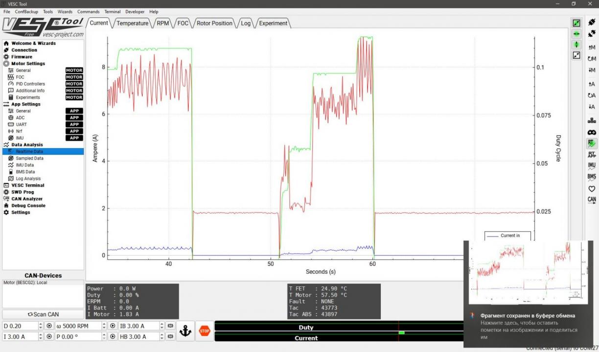
https://imgur.com/hf2rFII https://imgur.com/hf2rFII
either current sensor(s) or driver(s) are bad not fully attached to the board causing poor contact.
I would check the sensor readings individually first. It would also be useful to see bemf graph to make sure voltages are read correctly.
NextGen FOC High voltage 144v/34s, 30kw (https://vesc-project.com/node/1477)
on 5.3 the filter does not work for us?
Hakan Seray Şibik from Ankara.
Guys, I have a request from you.I want to contact emrah guven.
If anyone knows the e-mail address, if it can help, I would be grateful. Regards
hakan seray şibik.
seray