So I just bought one of those Xiaomi m365 kickscooters. Fantastic hardware, great user experience.
But it's a bit limp. (top speed of 25km/h is quite good. But it doesn't do inclines well with a 100kg+ driver)
So here is my plan:
60v upgrade.
VESC driver. (I might splurge on the v6. Though I really don't need even half of the power)
I want to make it nice so I need to integrate it with the scooters controls and lights. I suppose the best way to do this is to hook up a Microcontroller via CAN to drive the auxilary stuff? Maybe even a small display.
Particular features I need here are.
- Some way to drive the brake light. Either through VESC IO or CAN message. (Looks solvable. Probably configure slave VESC and listen for it's CAN_PACKET_SET_CURRENT_BRAKE message)
- The brake leaver switch should also engage full engine brake. (Partially solved. Set Speed set-point to 0 via CAN)
- Regen braking when letting go of throttle (Needs verfication that PID Speed mode kicks in brake)
- Power in and out on CAN (Solved: CAN_PACKET_STATUS current and duty fields)
- Voltages on CAN
- Temperature on CAN
- Speed governor mode would be really nice to have (Partially solved. PID Speed mode. No solution for set point hold. May need to put it into external microcontroller and drive VESC via CAN CAN_PACKET_SET_RPM)
- Regen brake strength via runtime setting would be nice too. (Solved: CAN message CAN_PACKET_SET_CURRENT_BRAKE_REL)
One thing I noticed while reading documentation and looking at screenshots.
There is a setting for regen currents. But I see no provisioning for over voltage protection. Suppose I drive downhill with a fully charged battery? Will it blow up my battery?
Battery BMS. I really don't want to go without one TBH. At least for charging. Coulomb counting vs. voltage monitoring would also be a great benefit.
Does anyone know a nice 10S BMS sized appropriately for a small kick scooter? Ideally with CAN bus too.
Does VESC have any provisioning ro play nice with BMS? I'm thinking regen braking again.
I will soon start buying hardware. But right now I want to play with the idea a little first...
Any tips and ideas are welcome.
[ Updated with results as far as I know them ]
I was mostly able to answer the question about brake button by 'buying' the config tool. (Will actually donate some money later)
I can use the ADC no problem. But how it works is still not quite clear to me.
When I select "Current No Reverse Brake Button" When does it brake? When I let go of gas AND when I press the brake button? Or only when pressing the brake button?
And of course the question remains, can I switch control regimes at runtime? (Between Current and PID Speed)
And in PID speed mode, is the set point always the ADC value? I would like a cruise control button that keeps the vehicle at the current speed until I touch brake or gas again.
It seems like I will have to think hard about a custom control APP I suppose...
I just realised that my whole assumption that I need the current control type might be wrong.
Is this whole "let go of gas to brake" behavior modern EV have perhaps already just a speed control loop?
I always assumed that would feel weird. But does it? Sorry if I thought it was more complicated than it is.
Ok, this exists. http://vedder.se/2015/10/communicating-with-the-vesc-using-uart/
Therefore all my questions about comms are answered. Though I still would prefer CAN for simplicity. I will investigate...
Oh, and another road-block. The battery I was thinking of getting (which will fir mechanically) is labeled 60V. Which is awfully close to the max voltage rating.
But it turns out, the max voltage is much higher. It's a 16s pack with 67.2V max voltage. That voltage will drop soon. But the electronics must be able to survive it!
So, how hard is that 60V limit? At what are the caps and MOSFET rated?
Hard.
If the DRV8301 gets more than +60V, including motor regen which will momentarily increase the battery voltage, then it will die.
If the IRF7749L2TR gets more than +60V, including motor regen which will momentarily increase the battery voltage, then it will die.
I believe the highest voltage recommended for the VESC 4 & 6 is 12s-13s. That's a maximum battery voltage of +50.4V to +54.6V. People have tried 14s (+58.8V) but have killed VESCs in the process.
There are a few people out there designing higher voltage VESCs but honestly, a 10s-12s battery is suitable for your needs.
As for a BMS, try this: https://github.com/DieBieEngineering/DieBieMS
Thanks, good to know. I would have been tempted to risk a little overspeccing.
Oh, dang. I was hoping I could at least go 14s. I have to work with the motors I got.
The powertrain is designed for 10S and performance is not exactly exciting. Almost no point upgrading if I only get 2-3S plus out of it. :/
It would be plenty strong and fast. But not the beast I was hoping to get.
I haven't actually seen any higher specced VESC out there. Do you have a hint where to look?
As for BMS. Seen that. I love it. But is it possible to get it as hardware anywhere?
I don't have the time and patience to solder it myself to be honest.
I have been wondering. If the only reason for over-voltage situations are transients and inappropriate brake events, should that not be easy to snuff out with a crowbar circuit?
Use a very high power FET and maybe a load resistor. And you turned this into a simple thermal management issue.
I am working on VESC clone with mosfets rated up to 150V 150A. Dimensions are 8cm diameter circle. Will it fit? I ordered Xiaomi m365 month ago. In two months I should be able to test it.
Hey fantastic. Keep me updated please. Did you also address the voltage limit of the DRV8302 chip? I'm actually less concerned about the FETs itself. They tend to be quite robust.But the DRV seems to be very sensitive. How did you address this?
I will have to measure the battery bay. I think it will fit. Worst case a little diagonal.
18650 cells are 65mm long. From the pictures I have seen there seems to be some space.
Let me find out exactly...
BTW. I suppose you already know this type of modification to the m365?
http://100kilowat.ru/product-category/xiaomi/%d1%82%d1%8e%d0%bd%d0%b8%d0...
This gives you a few mm more debth, which allows you to add a bigger pack (three rows of 18650 in staggered honey comb configuration)
I will use MAX15013AASA+.


some pics...
Fantastic. Interesting layout. I suppose the idea is to place that in the hub motor directly?
If you ever need a tester...
I can solder the boards even...
Can I follow your progress somewhere? Github, forum or whatever.
It is designed for boat water cooled motor. Something like this. I will post it here when I will be sure it works.

Which voltage regulator do you use to step down from 150v for control and gate drive?
LTC3638EMSE, 150V is absolute max mosfet voltage and not real input
So quick update. I need your help, I'm stuck.
First of all, pretty much everything seems to work great. Motor parameters get detected and it runs smooth and silent.
But in practice I'm very confused with the Amps rating.
Other people have experimented with the motor and 17A is generally considered ot be a safe max power rating. That results in over 500W at 10S and should be plenty. (Roughly twice overclocked related to stock)
But the driving is horrible, unless I effectively knock off all current limits by increasing them to unrealistic values.
Anything under 20A is barely drivable. If I pull the gas, it shows tremendous torque for a split second. But then crashes to zero. I suspect that is a current limiting effect?
If I accelerate very gently, it accelerates very limp and weak but it's somewhat drivable. The PID Speed loop is undrivable because it slams against the limit immediately.
So what is happening? Is Motor-Amps something else than I think it is? Are those currents indeed flowing but don't get turned into power?
I'm a bit lost. I can't just leave the current limit at 60A. Because that is overwrdiving the engine by nearly tenfold.
But then there is the ussue of peak current and sustained current. I don't mind massively overdriving the engine with peak currents in way excess of it's capability. It's just the sustained current that needs to be reasonable. Is there a setting for max and sustained current limits?
Should I look into the motor wattage tab? Does that limit more reasonable?
It's hard to experimentally determine those settings while spinning wheelies on my wooden living room floor. :)
Sound like you are using PID speed control mode, I would use current mode, it will give you smooth acceleration. If I remember correctly PID doesn't really like high inertia loads and would need to be tuned to the load.
As for current limits, someone made a boost mode that let you temporary increase the max current but it hasn't made its way into the firmware just yet. I would set the motor max current to the maximum for your motor.
Sorry I should have clarified. Yes I was using PID mode first, but since that slammed me right into current limits I changed to current mode.
It's still totally unusable. Performance is very low and any sudden accelerations make it disengage immediately (which is I probably some kind of hard current limit condition. I don't know what it is.)
PS: Is threa way to collect telemetry without a cable? I would like to see what's actually happening while I drive?
@Tilman Baumann: What VESC are you running? What control mode (FOC or BLDC)? How long are your cables between battery and VESC, and what's their area? What is your configured LVC (low voltage cutoff)?
Have you tried reducing the motor current limit to what the motor is specified to handle (i.e. no "overclocking", if I understand your usage of the word)? Maybe you're running into the same issue as several others here, with the motor saturating so that the observer can no longer track the rotor?
Also, if you're running FOC, what happens if you run BLDC instead?
> What VESC are you running?
Vesc 6
>What control mode (FOC or BLDC)?
FOC so far. But I need to test with BLDC this weekend.
> How long are your cables between battery and VESC, and what's their area?
Laughably thin and quite long. This is why I want to play it safe with the currents. (Stock harness)
> What is your configured LVC (low voltage cutoff)?
Whatever the wizzard suggested. I can keep a eye on the voltages next test.
> Have you tried reducing the motor current limit to what the motor is specified to handle
That is where I started. It's very weak and unusable. Makes no sense to me to lower the current. The more I give it the better it drives.
> Maybe you're running into the same issue as several others here, with the motor saturating so that the observer can no longer track the rotor?
Can you explain? I don't know what it is I'm running into here. Current limit is just my first intuition, since it goes away if I bump the currents.
BTW, the motor has HAL sensors.
You do realise you will get a voltage drop over a cable when you draw current through it? So when you draw current through a thin and long wire the voltage at the VESC might get low enough to trigger LVC throttling. To me it sounds like that fits the symptoms perfectly. Near LVC, the battery current is limited proportionally to the set max battery current, so that might explain why increasing current limits to ridiculous levels "improves" your situation.
Ah sorry, I misunderstood your question. The battery wires are nice and thick and short. No noticeable drop there. (Cutoff is at 31V. VBatt currently around 39V)
The motor wires are a bit dinky.
I ran some more tests.
The voltage doesn't drop much at all. That's not it.
In FOC mode with 20A I can easily grab the motor ans stall it. Really not much power at all.
I made a screenshot of the live data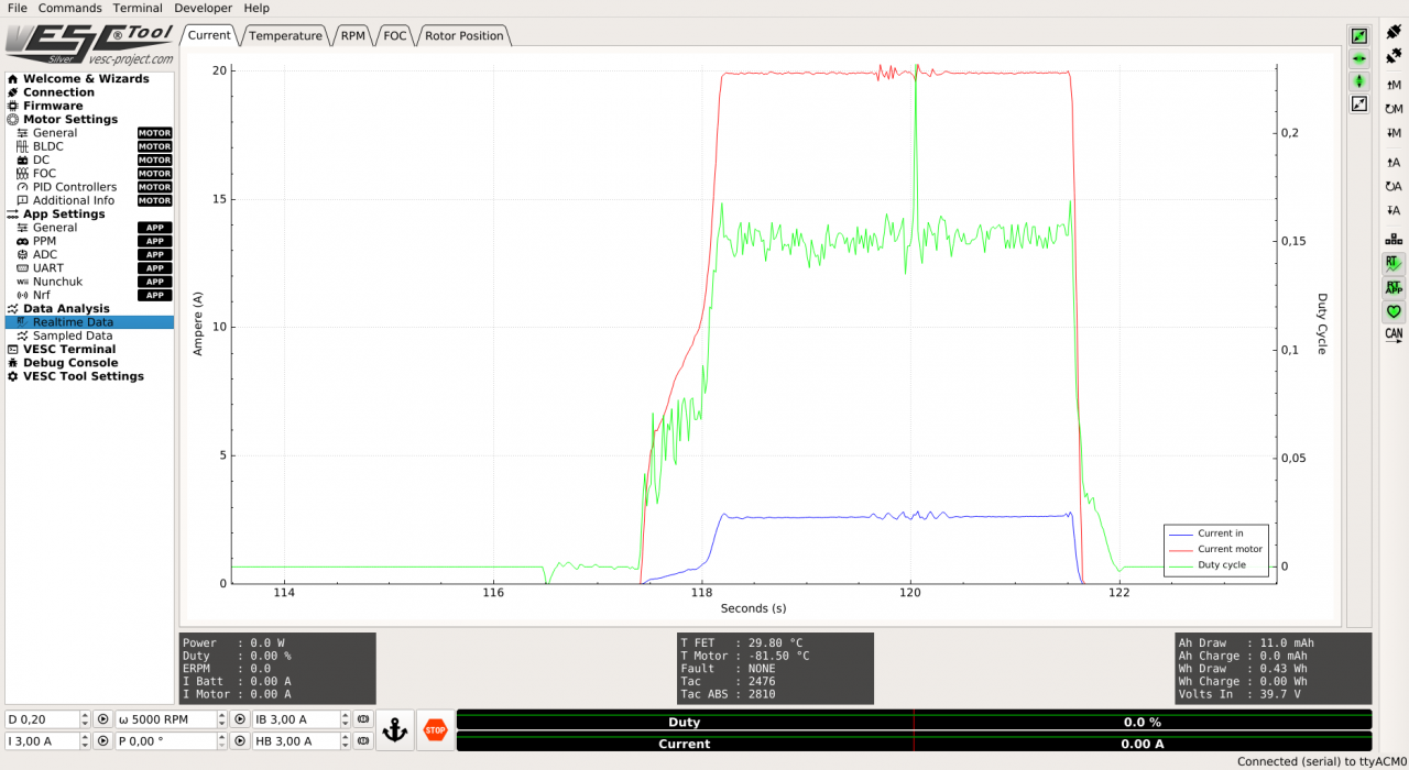
In that graph, what is motor current and current in? How can they not be the same? I kind of suspect that my error is there.
Motor current vs. Battery current. How do they relate?
I did some quick test in BLDC mode. It seems a tiny bit stronger. But it reacts badly to being stalled. Current values are all over the place. Feels very rough and dirty.
I did not go any deeper, since it still develops implausibly low power.
Current in and motor current are different because the motor transforms the voltage and current, its converting the 39V 2A into about 5V 20A as its running at a low speed. What are the motor specs reported by the FOC detection?
Yea, that was the knot in my head.
Of course once you think about it, it makes sense.
I just assumed battery current is 3xmotor current and never reflected on it.
I can report, I'm back to about stock performance. Great success.
Now I can play with the knobs to tickle out the last bit to make it nicer.
And I need to spend some time to understand the ADC input app. Perhaps I don't need to drive the whole thing via can...
So what was the problem?
I limited motor amps. But what I should have limited was battery amps.
Ii thought I would find it easy, but can you guys help me with a few hints?
Where is that Cruise Control button? (Same pin as reverse)
Next thing I need to play around with is analog brake. I'm pretty sure I got a hall sensor brake here. That should actually give me a nice proportional signal.
Then I can already see that I need to modify the logic of the cruise control button. I need it latching. If I have to keep my finger on the button, there is no point to it.
I think I figured it out.
Snipped from app.c
case APP_ADC:
        app_adc_start(true);
        break;

    case APP_UART:
        hw_stop_i2c();
        app_uartcomm_start();
        break;

    case APP_PPM_UART:
        hw_stop_i2c();
        app_ppm_start();
        app_uartcomm_start();
        break;

    case APP_ADC_UART:
        hw_stop_i2c();
        app_adc_start(false);
        app_uartcomm_start();
        break;
That boolean for app_adc() defines if rx_tx are used as buttons.
Ergo, if I don't enable UART I can use the rx_tx pins which are conveniently located.
Since I will be using can to communicate, that works for me.
Successful longer test drive today. ( Had to visit the customs office on the other side of town to pick up some china gadgets )
)
I haven't hooked up cruise control yet. Still a little unclear how.
Brake is on ADC2. The analog response is still a bit janky. The mechanical brake grips before it brakes electrically. Perhaps I need some negative expo on the curve.
No Off-Swich yet. No priority for me yet.
I noticed that the motor seemed to pull on for a few seconds after I go off the gas. Either this just feels unusual because it's coasting and not braking. Or there is some kind of cruise control like thing happening from time to time.
Also I notice the current limit still seems a bit restrictive. I will give it more. I'm sure it can take it.
how much was motor current on default controller and how much you have with vesc?
I don't know. I herd that up to 15-20 A are safe. But that was measured at the battery and with higher voltage.
I have set it to 15A and it was weaker the original on 10S. I have to experiment more. But I don't think it will be a huge factor unless I'm careless about stalling the engine or going higher voltage.
@Tilman Baumann So, you were able to use the VESC6 to achieve the same performance as the stock ESC. Do you notice any improvements to hill climbing or torque in general? Also, would you mind sharing your settings via screenshot?
The improvement on stock 10S wasn't very extreme except for the higher top speed and harder acceleration.
There are alternative firmwares out there which offer ver strong performance on original hardware. If performance is what you are after that is what I would do. Results are great. Potentially even better than with VESC, and you don't loose al the nice bluetooth and battery management features.
I'm thinking bigger. :)
Progress. 12s4p Samsung 30Q pack (3000mAh-15A per cell) with TinyBMS
Moin, moin, guys,
I have been following on this thread for a few weeks and I really love what you are doing. Obviously you know this inside out and I would like to ask on this topic as well. I have an older m365 produced in march 2017, so possibly with one fuse. I have read, this cannot be modded for higher performance. I myself am also a little, ehm... over 100 kg and would love some more kick if possible.
Is there anything that can be done on my 365? I would consider replacing the fuse module for the two fuse one, if that is possible or have fw update just for climbing, top speed is ok for me.
If more info is necessary, just ping me.
Thanks,
Vladio
As you introduced yourself with Moin Moin, there is a chance you speak German.
There is a rather active firmware modding community. Mostly organised in Telegram groups. http://de.m365.wikia.com/wiki/Telegram_Gruppen
Firmware details http://de.m365.wikia.com/wiki/Firmware
If you don't speak German, I think you can still make out the relevant links. ;)
Yes, with the older models you have to be careful with tuning. But there is still some room for improvements for you.
If you plan to tay on the original pack, there is no reason to do anything else than firmware hacking on the scooter.
Hello Tilman,
you are correct, I do speak some German, but wanted to keep the forum concise also for other people, I wanted to wink a little as your name suggested your roots :)
Thank you for the links, I will look at them at home, carefully, but one thing hit me, which is whether the one fuse system will take the increased power, or just burn out? Have you tried, anything like this on an older lady like this?
I am also considering the stronger pack, but later possibly, as budget is tight at this moment :)
Danke,
Vladio
The people in those Telegram groups can help you identify which battery type you have and help you selecting the right firmware modification that works with it.
Hi, I came across the forum while search for potential ways to upgrade the power/range of my Xiaomi m365 electric scooter. To be candid, most of what's posted is beyond my field of knowledge, but I am curious if anyone has yet been able to successfully upgrade the power/range of their scooter? I live in San Francisco and the power just isn't sufficient to make it up the hills and severely compromises the range. Thanks in advance for any insights you may be able to share with a a layman ;-) Steven
I got better torque just by changing firmware. CFW W for 850W and BMS 107 for full torqe after 50% battery. Here is tutorial https://www.youtube.com/watch?v=BawJjLjP3gE
I would think that the scooter already has a >80% conversion efficiency between electrical energy in the battery and mechanical energy. When driving up a hill, that mechanical energy is simply potential energy. When you complain about range, you are draining the battery, so there is not much you can do except get a bigger battery. (if you improve the efficiency from 80 to 85% you would for example extend your range from 10 to 10.6 miles... Not really a lot)
Follow up, here you can build your own custom patched firmware. https://m365.botox.bz/
Happy hacking
Anyone knows how we can disable the speed limit at ~32km/h? Firmware like CFW and patched firmware cannot do any, even if i select the option to remove hard speed limits at 35km.
When designing a product like that, you need to optimize a few things. One of the optimizations is that when you spin the motor at the max allowable speed, it will generate a voltage equal to the lowest battery voltage. So if you decide to use 10S LIPO at 37V nominal, max 42V, you need to decide to use a battery low cutoff voltage of say 32V. (using 32V instead of 30V will cost you 1% in range, but it is much better for the battery if not immediately charged). Then you will want your motor to generate 32V of back EMF at your max allowable speed.
That means that with a low battery, you are not going to have much headroom from the software-enforced max speed.
I haven't imagine that could be problem the generated voltage of the motor. Seems that you have deeper knowledge than me... Do you know any program to give me option to increase the lowest voltage of batteries?
Hi Guys,
I have found this forum with great hope upon your knowledge, I have recently purchased a M365 Pro running 1.55 firmware and immediately implemented the Gorka speed hack.
I am now searching for ways to achieve yet more power and have heard that a 50v battery can do this, is this indeed correct? I have also heard that adding 10" tyres also increases max speed but is there enough clearance on the front wheel to do this?
I have to admit I have no depth of knowledge that is shown in this thread but do find this all interesting, if there are any other upgrades you think I could benefit from then please do share.
I would ideally like to increase range, torque, max speed but whilst keeping the motor and battery somewhat happy.
Im eager for your responses.
Thanks,
TV
I largely have the same goals as OP at the top. I got a VESC6MKIV from Trampa, and successfully have FOC drive working with the stock 10s3p battery. I configured ADC input to the stock M365 throttle.
Below is my project outline...
Goal: Upgrade Xiaomi M365 scooter with more power and range, including updated dashboard with speed display. Optional: add back wheel motor for more power, if front hub motor has insufficient power (if runs too hot).
Means:
Control panel
VESC motor controller
Battery
BMS / Charger
Could you please share your parameters? I've been uncessfully trying to drive M365 Pro with VESC 4.2. It doesn't seem to have enough power with my settings and when I try to set higher current limits, battery's overcurrent protection starts kicking in.