Hello, I made my own 4.12 VESC where I basically just changed 50V to 100V ceramics, a ferrite bead, and a TVS so the VESC could work more reliably with a 12S pack. Also did my own layout so all transistors are on the same side so I can put a heatsink on the bottom of the board. Of course, it doesn't work.
FW 3.34, Hw 410, UUID 52 00 4E 00 18 51 36 34 32 35 34 36. Motor is a 5065 270Kv.
In VESC Tool, if I command 10% duty cycle the motor cogs around loudly and slowly. It does not enter controlled commutation mode (where it commutates from phase sense), and does not throw any codes. If I use any other mode, such as I or w, the motor jerks then stops when the 10A power supply current limit kicks in and it throws an undervoltage code. I interpret this as a symptom of the motor consuming lots of current from being driven incorrectly, ie without the supply limit, the driver would smoke the board and the motor.
Something I noticed is that phase B low side FET never seems to go inactive. Here are the phases as it is operating in open loop commutation mode (Phase A red, B Yellow, C green):
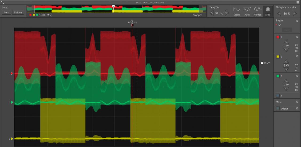
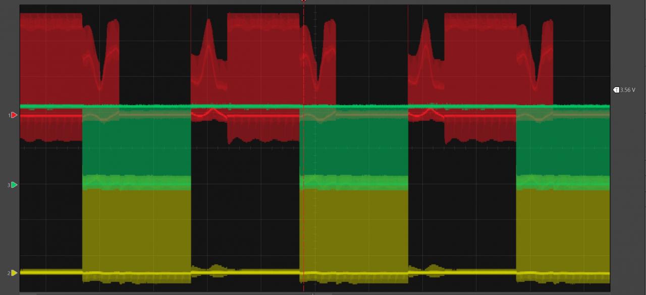
The commutation seems like its missing two steps: 'A+ C- Bsense' and 'C+ A- Bsense'. I assume this is some kind of startup technique? The waveform looks very wrong... Here is an image of B low drive always being on (Phase A red, B yellow, B low drive green):
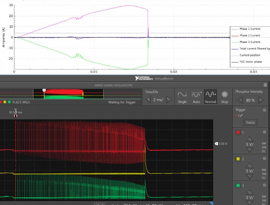
Here is the current capture from the sample tool and oscilloscope of the phases when I run the motor in current mode set at 3A:
I suspect the problem has something to do with the un-driven phase stuck at 0 instead of floating so the vesc can sense it. This looks like a software problem but it is more likely a symptom of something I messed up. What might cause this? Why doesn't it try and commutate with all 6 steps? What other data should I investigate?
Maybe a soldering (or routing) mistake? Do you get a gate drive signal all the way to the B phase MOSFET gates?
It sounds like an interesting design! Can you post a picture of the board?
I can see the gate drive signals and they all match. No dropout on the gate drive like the bootstraps aren't big enough. The gate drive signals match the processor outputs. And the processor outputs are strange, but I think that is part of how the software works. I tried spinning it with a drill. Here are the back emf waveforms, and current waveforms with the brakes on:
Here is a picture of the board. The diameter is 2.28" to fit in a 2.3" tube. Also has RS485. Haven't been able to verify that it works comfortably at 12S.
I can get my 4260 motors spinning using a lab power supply set at 25 V with 1 A current limiting without problem (VESC motor current limit at 20 A).
I took a closer look at the schematics: VESC4.12 connects the shunt for phase A to Sx2 and the shunt for phase C to Sx1. You do it the opposite way, if I'm not mistaken. I guess that could cause a fair bit of trouble? :)
Nice board BTW, thanks for the pictures!
You *should* be able to fix this by changing
to
in hwconf/hw_410.h. Just don't blame me if I'm mistaken and fires or other interesting things appear because of this change. ;)
Hi,
I have made same mistake the first time. You also have to change code in mcpwm.c to injected ADC if you use BLDC, for FOC it should be enough what @arvidb said.
Original mcpwm.c:
After changes:
Martin.
Oh man wow thanks guys! I hadn't gotten I to the code much yet but I am glad this is fixable! Another question: I noticed when I compile the source off the Vedder github, VESC Tool says it's wrong software- I assume that means there is a more correct repo? Is there a best place to get everything so it works together?
Vedder's github is the authoritative repo as far as I know. That's what I've been using. I build VESC Tool and the firmware separately, then select custom firmware in VESC Tool when flashing (I think that's what it's called; the option where one have to browse for the firmware file). Then select the bin file from the firmware directory, I think it's called bldc/build/BLDC_4_ChibiOS.bin? Might be mistaken though, I'm not at my build computer now.
I swapped the signal lines with a little soldering work- and the motor is spinning in FOC mode now!! Thank you for your help, I never would have found that error.
Strangely enough it still won't work right in sensorless BLDC mode. It spins, but its still doing the 4 step commutation thing, skipping 'A+ C- Bsense' and 'C+ A- Bsense'. Feel like this is a startup thing that it does while it looks for a zero crossing (if VESC works like other BLDC drivers) but its not getting into delay or integrate commutation mode. Are the fields:
used to get into commutation mode? I've tried a lot of combinations but I haven't got it to commutate properly yet. It's spinning just fast enough to see zero crossings, I can see them on the scope. It's identifying the phase its on in the sampling tool as well. If you have any tricks I would appreciate it.
Have you noticed that in HV4.12 phase SENSE1 connected to phase 3 and phase SENSE3 connected to phase 1?
Yes, that is the case. I attempted to correct the schematic error by swapping SO1 and SO2 outputs to the STM32F4 adc. SO1 now goes to pin 26 (adc 8), SO2 goes to pin 27 (adc 9). This connects phase 1 current to pin 26 (adc 8) and phase 3 current to pin 27 (adc 9). It does run properly in FOC mode- is that evidence that it is wired right or does FOC mode have some symmetry where it would run anyhow?
Motor used to not spin in BLDC. Now it does, but does not 6-step commutate. Seems like something changed for the better but I must still have an error. Been looking at the schematic all day trying to see what it might be.
I think what e-biker is saying is that VESC calls phase A voltage sense "SENS3", and phase C voltage sense "SENS1". Look at the DRV page in the VESC schematics: H1_VS is connected to net SENS3, and H3_VS is connected to net SENS1.
This means phase A voltage sense is connected to STM32 pin 14, and phase C voltage sense to STM32 pin 16. You do it the opposite way. So it's the same problem as with the current sensing.
Some people are not able to be helped. Today, I am "that guy". Thank you arvidb and e-biker for helping me to see that which my eyes could not see.
You're welcome. :)
Keep us updated on your progress!
Hey nickkw1881,
I saw that you get a sinusoidal plot for all three phase currents in VESC tool, How did you manage to do that? I don.t get the sinusoidal phase currents even when I use FOC mode. Also, is there a way to log all three sinusoidal phase currents?
You can get sinusoidal plot if you drive motor with load
The bots really love this thread!