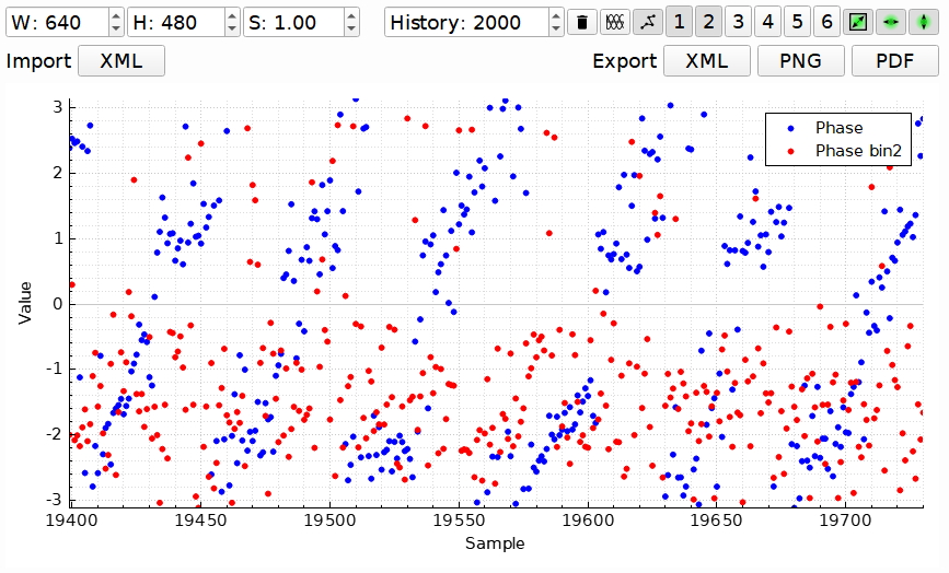
I tested HFI today on an e-bike geared hub motor, and was getting promising but intermittent results.
I followed Benjamin's video and used the plotter to see if I could tune the HFI parameters for better results.
No matter how much/little voltage I give it, the result for 'full brake' looks like this:

Any advice?
I will try a different motor and update this post if there are any changes.

I'm also seeing strange behavior after updating to 4.01. I don't know if it's related to HFI, but want to post in case someone finds it helpful. I have an ebike as well, and it's exhibiting weird resonance at higher speeds above 80% duty cycle. Haven't had an issue with any previous 3.xx firmware versions, and I haven't made any hardware changes before updating to the new firmware.
Here's a video of it happening, not sure if you're seeing anything similar to this? https://www.youtube.com/watch?v=jLUOK-dVWSw
Ebike Ninja, I believe this is the result of too low a signal to noise ratio and the VESC thinks the motor is spinning when in fact it's not. I.e. the signal to noise for HFI needs to be better by possibly changing (increasing) the HFI voltages or using a different type of motor. I do notice at high HFI voltages the motor tends to get stuck spinning very slowly and won't switch over to sensorless. Fun to play with!
Had exactly the same problem yesterday with my Surron Bike. It has nothing to do with HFI.
Go to FOC -> Advanced -> Current Controller Decoupling and try out the modes. In my case it solved the problem, hopefully in yours, too!
Link to forum post: VESC help offered for private persons and companies
Website: www.electricfox.de
after some tinkering with voltages, i get this
Update: Switched to a different battery pack (12S) and raised the HFI voltage to 35V, and It works perfectly! Bit noisy, but just as strong startup torque as with hall sensors. I'm impressed. This is me turning by hand in handbreak mode:
And this is slowing the motor as it spins:
In conclusion; large motors e.g. e-bike motors can take a really high HFI voltage to even begin to saturate.
I've tested it with big motors and, basically, HFI doesn't work at all on my hardware at least. Regular sensorless mode starts almost flawless without the load though.
It seems that HFI measurements depend very much on very accurate current measurements within 0-1A range and my current sensors have a resolution equivalent to a 1.4mOhm shunt without any amplification allowing measurements above 1000A though.
NextGen FOC High voltage 144v/34s, 30kw (https://vesc-project.com/node/1477)
Hi, i have very similar results with a lot of noise in the graph, the problem is that my battery voltage is never higher than 16v.
At 15v hfi voltage the graph looks like this:
There is no chance to make it work with low voltage batteries ?
Got some very odd HFI results on my old V1.2 hardware. Works great on V2.1 though. I don't really understand why the value is changing in what looks like the right shape, but its not at the same scale as the initial measurement. Also odd that the red is half the rate of the blue.
V1.2
So turns out the problem was imbalanced current shunt measurements. Tuned them all to have pretty close resistance by adding solder to them till they all read the same current.
Sorry if this is a stupid question, but how did you measured the shunt's current? Do you measured the resistance?
This is how mi HFI looks like:
Any pointers on hwat can I do to make it better? My values are :
SV 20
RV 4
MV 10
My battery will not give more than 32 V