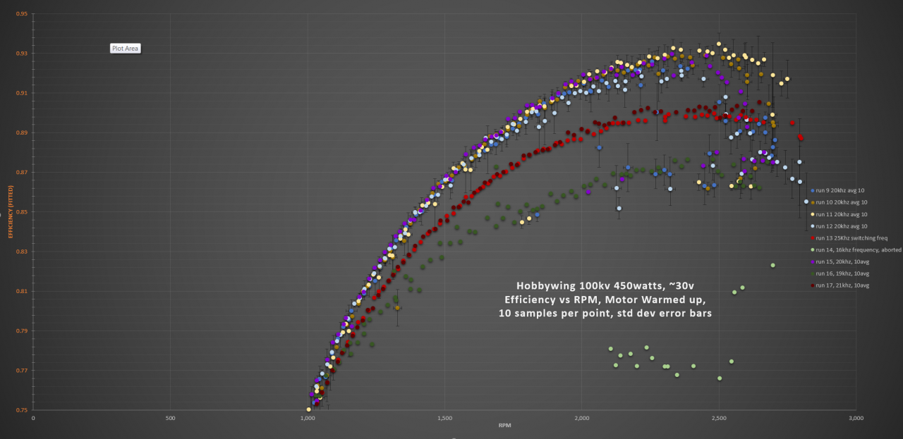
Looking for some thoughts on this data. On my dual vesc based dyno, i'm getting this data when changing switching frequency. Anything other than 20khz is distinctly and repeatably lower efficiency than 20khz. Why would this be? Is there something in hardware or firmware that's preset for that switching rate? Anyone have any ideas?
Interestingly, the test motor seems to be more stable and consistent above 20khz, but less efficient.
Could get more data easily with community setting recommendations in VESC-TOOL.
PS, this is with a FSky 6.6.
More conversation over here -> https://www.electric-skateboard.builders/t/changing-foc-switching-freque...
Tested another motor, and got pretty similar results. Granted, by test setup isn't ideal, but there seems to be a trend.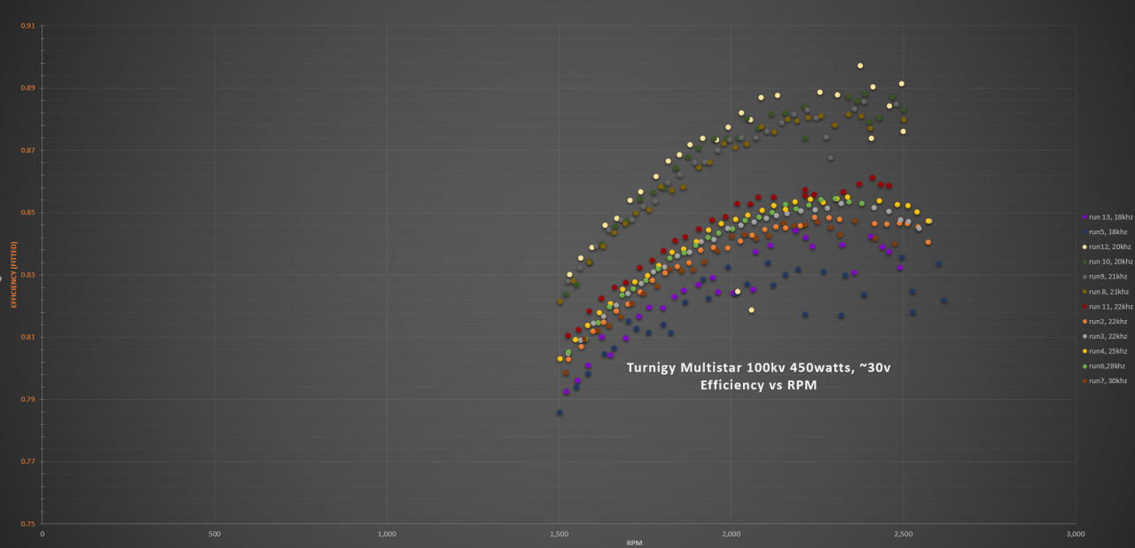
I've noticed the same thing. I noticed at very low loads the peak of efficiency can be as high as 25kHz fsw. I haven't looked much at the voltage sensing, but I looked at current sensing a lot and it seems that in trapezoidal mode (possibly foc mode as well) the VESC samples current only once during each PWM cycle. You can see a big difference in the quality of the waveform if you sample data at 20kHz switching vs 40kHz switching. The slower you PWM, the less data points the VESC has to predict the rotor position, and the less accurate the VESC will be when commutating. Also in trapezoidal mode the VESC6 is still sensing during synchronous rectification, which needlessly limits the duty cycle on HW which doesn't have to have a limit.
The higher the PWM frequency, the more samples the VESC has so it commutates accurately and efficiently, but also there are more on-off transitions, which heats up the FETs. Balancing these two numbers gives a peak efficiency around 20kHz. What would be GREAT is if the ADC sampling frequency could be doubled. With the VESC6 high side sensors, it should be possible to sample current during both high-side-on and synchronous rectification. This sounds easier than it is, I don't know how to sample twice at during each pwm phase at a constant interval without sampling during the switching event at a particular duty cycle.
I have a Castle ESC (Phoenix Edge lite HV120) that runs at about 15kHz using bipolar switching. It has a single high side input current shunt. It runs so smooth and efficient, and a few hundred RM faster than a VESC6 at no load! I assume it must be sampling multiple times during high-side-sw-on to gauge voltage and phase current.
Edit: I looked at the foc code, and it looks like the VESC also senses the adc once per pwm cycle in foc mode. If you have 3 shunts (VESC6) and select "Sampling in V0 and V7", it does two adc readings per pwm cycle. Once when the high fets are all on, and once when the low fets are all on. So I think the 3 shunt VESC6 will run with equivalent control precision at 20kHz as a VESC4 at 40kHz, but with 1/2 the switching losses. But if we want to run ultra efficient at 10-15kHz, I think we will still need to find a way to make it do more samples.
Good info nickw1881!
I have been using the "Sampling in V0 and V7" mode on my flipsky 6.6. I had been gathering current, voltage and rpm data from the vesc via serial, but after some prompting on the other forum thread at https://www.electric-skateboard.builders/t/changing-foc-switching-frequency/30928, i realized that the vesc was doing a pretty terrible job of sampling current at the battery. Apparently it's back calculated from the shunts, and this is only done (as you point out) at most a couple times per cycle. I compared my inline pololu current sensor to an external unit and the vesc and the vesc was reading around 10% lower, but that varied during a run between around -12% to -8%.
I updated the dyno to use external rpm, current, voltage sensing. It also now sends a ppm signal for control, and doesn't need the power limiting build into the vesc to simulate my power limited application. Code now controls the duty cycle to prevent overshooting the selected power limit.
Anyhow, the new data is pretty interesting, and likely invalidates the old graphs above. I've only done one motor on the flipsky. The flipsky 6.6 has since quit working and will be going back for warranty (wish me luck). For comparison i also ran the same motor on a matching hobbywing foc esc and overlayed that data against the vesc 6.6. The hobbysing esc which claims to run foc at 30khz is outperforming the flipsky6.6 on the same motor by around 4%. I forgot to run these new tests at full range (so they start at 2000rpm, not 2500rpm), but the trend is clear. Both tests had the same calibration constants for current voltage and force/torque calculations. It's certainly possible my sensors aren't calibrated perfectly, so the absolute efficiency % might not be quite right, but the relative difference should be unaffected.
Green is three runs on the hobbywing esc, others are flipsky vesc 6.6 at varying switching frequencies. All with the same sensors and calibrations settings. All at 450w power limit, though now that i think about it, the vesc tests had an internal limit, and that's somewhat inaccurate due to poor current sensing. Could be as high as 500w on the vesc tests. Once i can get my hands on a new vesc i'll compare with the same external power limit. There's always something...