Hi,
I was requested to share BOM of my board protorype that works with VESC software so there it is.
Kickad project
https://github.com/antonchromjak/MINI4
BOM
https://github.com/antonchromjak/MINI4/raw/master/BOM.txt
Test at 24V
Test at 48V
Some photos:

next project: vesc up to 100V 150A
Great work....!
i was curious, for driving your FETs with 3.9R (as opposed to 4.7R for VESC 6), and also having about HALF the Gate to Source intrinsic capacitance,
did you have any FET Driving Timing issues....? like did you need to modify the source code to match your hardware?
for example in file: mc_interface.h #define HW_DEAD_TIME_VALUE 60 // Dead time
I use now 2R. This driver work with only 5V. Dead time value was equal to value I needed to compesate so I lowered this in code to 20 so I can leave default 80ns compensation.
Just example: 5V / 3.9R = 1.3A, 12V/4.7R = 2.6A, but there are olso mosfet internal gate resistance and driver resistance.
LM5113 has 0.6R pull down and 2.1R pull up, estimated mosfet resistance 1R (not specified), so we got
max turn on current: 5V/(2.1R+1R=2R)= 1A
max turn off current: 5V/(0.6R+1R)=3,1A
I also use 60 gain amps so there is need to change code. But if you use 20 gain amps and R0005 shunts you can use same firmware as vesc 6.
Great work.
Replace R6,R7,R8,R9,R10,R11: 0603 3R9 to 2R?
Yes
Hello Anton,
nice project, I like the design and size of your controller. I tried to opeb the Schematic, but Kicad said, your schematic use an old version.
Which Kicad Version did you use?
Did you use the VESC Software for HW_VERSION_60?
Or can you provide a PDF?
Greeting from Berlin,
Andre
Very nice work, thanks for sharing :-)
When you have finished the hardware, it works well and you plan to make more of it (and possibly start selling it) we can add a configuration file to the firmware for your hardware and maybe also include it with the vesc tool releases. It is also possible to override the default dead time value in the hardware configuration.
thanks :-)
It was in plan. I got 100pcbs but just have no time for assembling.
I am working on version for 150A with 150V MOSFETS for boat. Little bit complicated with 6 layer pcb, 8cm diameter.
I got hard time creating configuration file because of relations in MAKEFILE so I just edited VESC6 file for my testing. Some hints what to add?
Hi
Windows Version: (2017-12-12 revision 5f6f03b16)-makepkg, release build
yes but you have to change gain and shunt resistance according to components you use
https://github.com/antonchromjak/MINI4/blob/master/MINI4.pdf
I love that round one!
Thanks. I got two new 10kW watercooled motors for new test bench for this project.
Hi
I am Oleg from Klaipėda University Robotics Club, I look forward for BLDC use in Robot Sumo, and I already found this nice Benjamins solutions, I heard of a long ago from my team mate Martynas Lukas rumors about it after one of RobotChallenge competitions that some Sweden guys made nice ESC for perfect torque and speed responses and applied them into Sumo. So finally my search is satisfied. Where I might order these assembled or non-assembled kits? I mean MINI VESC would be perfect to my project, I think. And I am a bit to lazy to redesign it or manufacture it. Tried JLCPCB, the manufactureablilty of it is not possible due to their capabilities, OSHPARK kind of expensive for today prices of PCB.
Oleg,
how many pcs you need ?
Hey Anton,
what is the max voltage and current rating for this?
I want to try it with a 3kW motor @ 36V and see how it works.
Do you mind explaining the differences between this and VESC6 a little more? For example where would the mini be more appropriate? Can the mini4 do FOC? I know VESC6 uses DRV to drive the mosfets, why did you decide on the LM511 drivers, could you save space using DRV and getting rid of shunt amplifiers?
I am trying to decide whether the mini4 or VESC6 would be better suited for my application.
Thank you!
Does it work ok with those 5v GaN FET drivers? They aren't really meant for Si MOSFETS, though looking at the FET datasheet the RDsOn isn't too bad at 5v. You could easily replace the fets with GaN fets, though I don't think the STM32F405 PWM can really exploit their switching speeds. In theory with 100khz switching speed or so you could probably eliminate the need for electrolytic caps entirely, improving efficiency and power density.
48V, 15A ~20A continious, 30A burst
If you are space and weight restricted.
Yes, control logic is same as VESC6.
they are smaller, more robust and can work with 2S battery without converter
no space benefit, point of VESC6 is to use phase shunt amplifiers
Go for VESC6 if you don't mind size and weight.
Yes, I can't get it work with 12V drivers yet.
You should try something like these on it, half bridge in one chip and would take up less room than one of the existing mosfets. You could fit more capacitors with the free space.
http://epc-co.com/epc/Products/eGaNFETsandICs/EPC2102.aspx
Have you ever used those GaN or similar?
What about light sensitivity as it seems to be a bare die chip!
What about mechanical things to pay attention, flexion,... and other important things.
Have a Nice Day.
Thierry
Most important parameter of mosfet for motor control after max DS voltage is drain to source resistance RDS(ON). NTMFS5C604NL is 1.7mΩ. EPC2102 is 4.4mΩ so for same current it will produce 150% more heat or for same heat 35% less current (roughly).
It is possible to make half size VESC of this MINI4 for very low power but WHY? Is there demand for such application? 5 grams vesc 20V 20A ?
You would be surprised, by the time you take into account time spent in the miller plateau due to driving it with 5v, gate capacitance, the mosfet package having much higher thermal resistance and various other factors the RDSon advantage can be quickly eroded in some situations. It would depend on the load and switching frequency to some degree, if you are not running max current continuously the reduced switching losses make a difference. These 6x 2mOhm 60v ganfets would likely win in every situation over the Si MOSFETs but then you forgo the convenience of a half bridge in one IC http://epc-co.com/epc/Products/eGaNFETsandICs/EPC2031.aspx
Please Lizardmech. Have you ever used those GaN or similar?
What about light sensitivity as it seems to be a bare die chip!
What about mechanical things to pay attention, flexion,... and other important things.
Have a Nice Day.
Thierry
In case of MINI4 max current is limited by max thermal dissipation 2W. So at 20A 48V and 20 kHz switching looses can be 20% and total 2W heat. At 5A 48V 20 kHz heat will be 0.2W and switching looses 80%. But who cares about looses at 0.2W dissipation if you limit your max current by using some exotic mosfet.
I haven't tried the epc GaN fets yet, I have some gan systems 100V ganfets,but they are 8 mOhm, they seem to be focusing on their 650V models for now, while EPC focus on 40V-200V. They aren't light sensitive, those EPC GaN fets are actually also rad tolerant and can go in space. I'm not sure about PCB flex issues, it may be mitigated by the small footprint. The biggest issue is gate drive voltage the EPC models require 5v and aren't tolerant of much more than 6 or 7, the Ti drivers on this board are designed to clamp it at 5v max but you still have to make sure inductance between the driver and get overshoot. For some reason the GaN sytems models use 6V and can survive 10V meaning a different drivers ends up being better for them.
The other thing that is complex is trying to calculate performance vs silicon mosfets.at first glance they don't appear much of an improvement or RDSon looks a little high but by the time you calculate switching losses, how easily they can be cooled and many other variables they can end up being better. Its so complex I think just building a prototype is quicker to compare. Where they gain a big advantage is if you can design everything to take advantage of them, for example running them at 100khz is no problem, at those sort of frequencies its often viable to remove all electrolytic capacitors and use only very low ESR ceramic or film capacitors which offers considerable reduction in heat and losses. Additionally very low inductance coreless motors can easily run and extreme ERPM speeds become possible further increasing motor power density.
How is your next project going?
layout is complete. Had some troubles finding fab that can make 6layer pcb with 2oz cu and blind vias in top-in1,in2-bot,in4-bot but i found one so after month should do some testing
Just some phptos
Nice!
So are you selling them yet or are you just teasing?
Oh, that looks very promising. My only fear left is the firmware. If there would be a Mini4 version in the official VESC Tool, I would probably order one. Any update on that front?
It's hell to hand assembly them. It take me 5 hours from parts and pcb to have fully tested board. I work on openPnP machine so I can keep my mind sane and you happy. Olso price should drop significantly.
No update.
Yeah I can imagine hand-assemby is not feasible for something you want to sell.
An OpenPnP pick-and-place sounds like a cool project. :) Good luck!
I don't want to think about how much of a pain soldering those caps would be.
I tested MINI4 with AC servo motor rated at 50W 220V 0.4A.
And it works! In sensorless mode without encoder or halls connected. VESC TOOL is showing 60mA motor current at 95% duty cycle. Shunts are same 0.5mΩ. Supply voltage 53V.
Very cool!
Nice 16s LiFePO4 pack. I wanted to make an 8s pack out of ANR26650M1B cells, but just couldn't get the solder to wet them. No problem with 18650 li-ion cells though...
Is this the 100V 150A version, or is that your next project? How much do you plan on selling these for, and when do you think you'd be able to start selling?
This is 48V version.
I am still waiting for pcbs so I expect at least month. When I build one I will have exact number but expect it to be in 500 EUR region. 6 layer 2oz boards with sequential lamination are very expensive. Keep in mind that board is 8cm diameter and needs to be watercooled to deliver 150A.
How did you plan to mount the Mini4? There are now holes in the PCB for screws, are there?
Thanks
Werner
It's not meant to be screw-mounted. In my application I will cover some parts with capton tape and push it between two alluminium blocks with silicone pads.
Hello anton,
i work for few month with these vesc, i use it in my hobby airplaine and e-bike, if you have a few pcb´s i can assemble them, i owner of an electronic company with all equipment like pnp machines, reflow soldering...think one pcb runs less than 4 min´s :-)
Only let me know...
Best regards,
Thomas
Interesting project, thank you for sharing.
Hey Guys,
I ordered a bunch of three PCB's for the latest revision. They should arrive within the next two weeks.
The parts have already been delivered.
So once everything is here i will give them a spin with our Oven.
Time to build the first selfassembled VESC
@anton Thanks for pointing me to your new Thread. Very nice work!
Hi,
Thank you for sharing the design. I have modified the pcb (but not the schematics) to move all the mosfets to one side and added mounting holes. Unfortunately it does not work very well. The 5V rail was extremely unstable, which I did try to work around with a linear regulator, which also was quite unstable and the only way it works is to use a 5V lead acid battery. Otherwise it reboots almost immediately when starting with motor current >10A. I power the ESC with a 22V 6S li-ion battery, and it is swinging between 17V and 40V. The cable to the battery is 30cm long but I have a whole bunch of capacitors of all sizes mounted.
Maybe someone here has an idea of what to do to get the boards working. I already changed the Mosfet gate resistors from 3.9R to 2.2R.
Thank you very much!
My experience working on commercial ESC project taught me that for high current application you need to pay a lot of attention to PCB design, routing etc.
Your issue is power related, I would first try to determine if the issue is not the battery related. Some battery just not as good as it says. While testing I usually use a special made lab power supply attached with several 10000uF/100V power capacitor to give enough juice that a good battery can come out, so that I don’t rely on battery for testing.
Put an oscilloscope probe on one end of your battery cable and the other probe on the other end. Run your motor and try to reach 10A, check how much of a voltage drop caused be the cable. If the voltage drop is too great either change the cable or increase the capacitor. From my experience 10A continue current needs at least 500uF capacitor in combine (All capacitors need to be low ESR type). Capacitor is crucial in all ESC. Just try without capacitor, you may even see transient negative voltage in the main power rail, which surely throw your MCU to wonderland or kill it.…
Just my 2 cents.
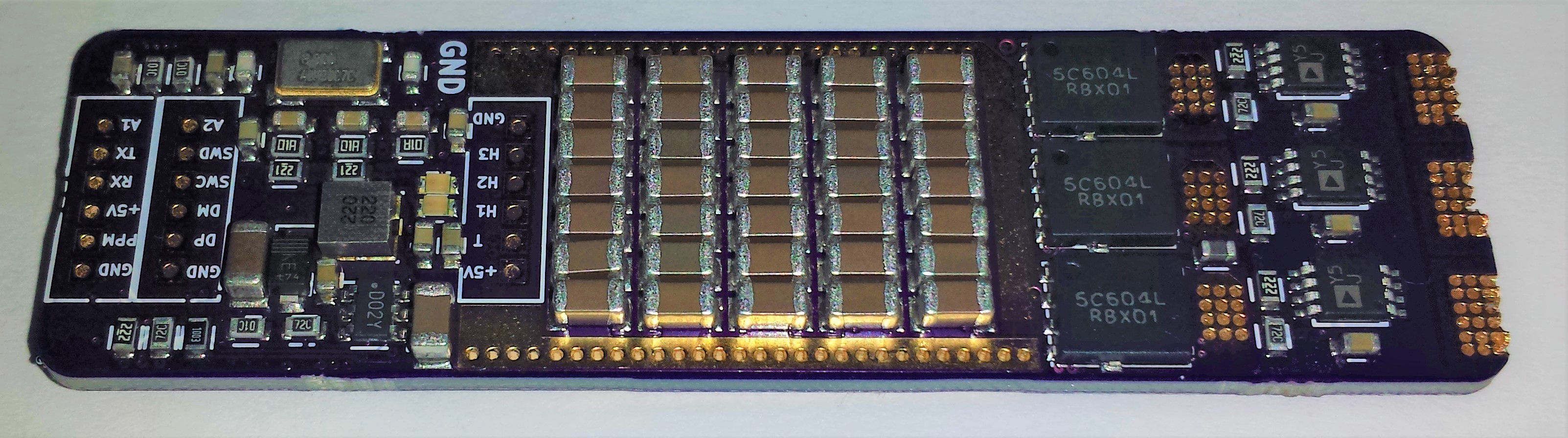
I can say the problem is 100% that you have no capacitors on your switching nodes. So the high current will cause horrendous noise. If you see the original MINI4 has 57x 2.2uF ~120uF of ceramic capacitors. To provide the very high current when the mosfets switch. Since you have no capacitors your input probably browns out, or just sees an insane amount of noise, hence your microcontroller resets.
This video that Benjamin made is really helpful. I suggest you download LTSpice and the simulation he provides in the description. Then play about with the values yourself.
There are a number of issues on routing I can see on that screenshot. But I can't read any of the names so not exactly sure if anything else is weird. I can look at he kicad files if you want.
Hi,
thank you for your interest in helping me. On the board I have 3pcs of Panasonic EEUFS1V152 capacitor as well as 10uF+100uF ceramic + 470uF aluminium cap capacitor in parallel, 2 of the large ones mounted in the holes on the right and one directly as bridge over the mosfets. I also tried with Anton's original MINI esc in parallel to mine and it still does not work. I have used a shitty hobbyking simonk esc before and it worked well with the same cables and battery.
Best regards
Did you change the values for current and voltage sense in the firmware?
I remember antonchromjak mentioned somewhere in his another MINI4 post he have changed current sense resistor value. Also some value changes in firmware.
Yes, I do use the firmware provided by Anton to me, it has the values changed.
This looks like an awesome project. What is the Quiescent current for the MINI4? I have a low power application in mind that needs to squeeze every drop out. I'm considering switching from the F4 to the L4 and perhaps optimizing the FETS for a more low current application <10A. Thoughts?
Still planning on selling a few of these?
~ Vbatt/(39k+2k2)
not in near future
Hi I'm looking to get a couple of these boards made to drive a small Gimbal motor (https://hobbyking.com/en_us/2206-140kv-brushless-gimbal-motor-ideal-for-...). I'd want to get much lower power Mosfets and I probably would n't need as many capacitors. Any other considerations I'd need to take into account?
Thanks
Pages