Hi guys,
I need some help in setting up VESC in a generator application. Below is a brief description of my setup and findings so far.
Mechanical Setup:-
I have two motors (one I am using as dyno and other as generator) and both are mechanically coupled together, as shown in the figure. I have a custom build controller running my dyno at desired RPM which I set via UART (LabView application). The other 48V motor (which is being used as generator) is attached with a VESC but there isn't any DC source attached with it. I have only connected a load (~6.6 Ohms) on the DC bus.
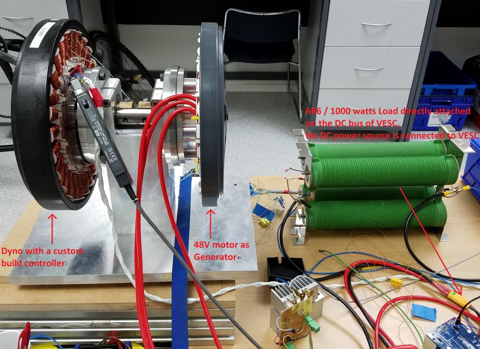
The parameters of the 48V (1.5KW) motor which I am using as generator;
Rs = 0.141 Ohms, Ls = 1.05mH and ~15 RPM/V
VESC Tool Setup:-
Motor max. current = 60A; Motor max brake current = -80A Battery max. current = 60A; Battery max regen. current -80A.
The ERPM max I have set is 3600 (200 RPM * 18 pole pairs)
The control type/mode/application is ADC
No DC is connected to VESC, it powers up once the generator starts rotating above 150 RPMs which puts about 14V on the DC bus of VESC.
Results so far:-
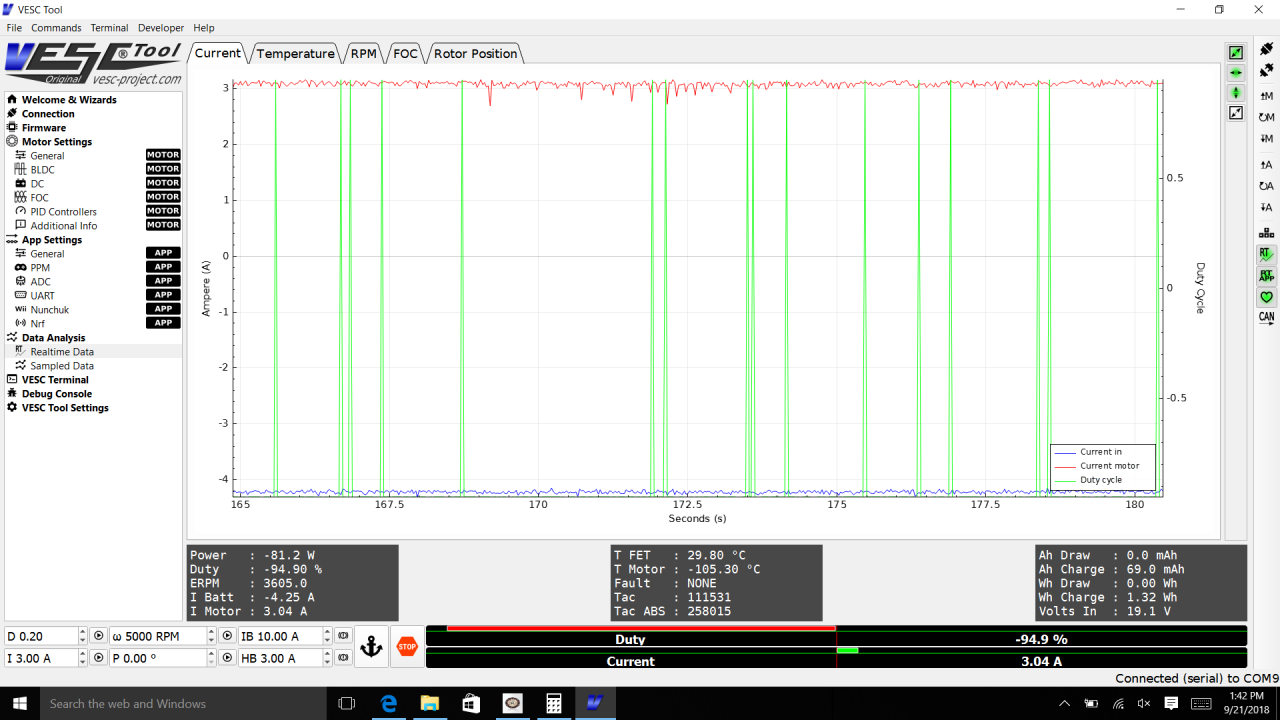
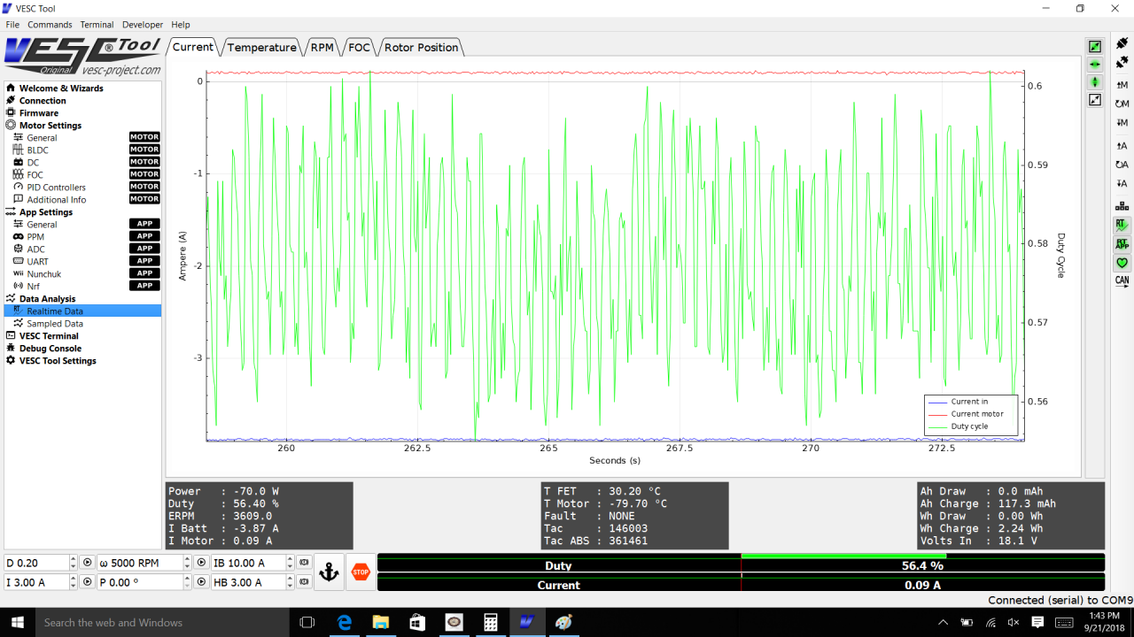
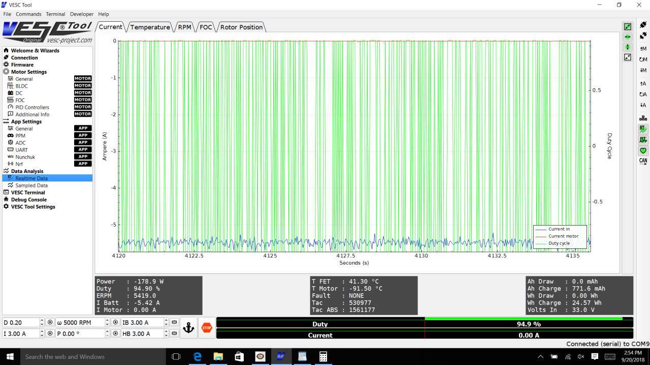
I have tried all the control types/applications but only two seem to work; 1) Current Reverse Center 2) Duty Cycle
But in both of them it looks like VESC is not behaving as I expect it to behave. It doesn't brake hard meaning it doesn't give me any decent power/current. In both modes/control types the maximum I get is
18V / -3.8A @ 200 RPM and around 33V / -5A @ 500 RPM
When I move my potentiometer (on ADC1) the values do vary but that's the maximum I get. They don't change no matter what brake (or regen.) current I set.
I have tried to use 'Current No Reverse Brake ADC2' but it doesn't do anything. In the VESC tool the CH2 remains grey. I can see its voltage changing when I move my pot. but it doesn't turn green and hence this mode doesn't work.
-- Current Reverse Center @ 200RPM
-- Duty Cycle @ 200RPM
-- Duty Cycle @ 500RPM
I have even tried changing the IB and HB (after turning off the 'control Type' under 'App Settings') but no matter what value I use the 'I Batt' doesn't change much. It remains between ~-3A to -5A (@200 RPM).
Can someone please shed some light on why it is behaving like this? or What I am doing wrong? and what should be the correct set-up (both hardware and vesc configuration)?
What I want to do is; to vary the generation energy depending on a command from UART or with the help of a potentiometer on the ADC without changing the RPMs.
I would really appreciate a quick reply. Thanks a lot in advance.
My biggest bet would be on that the generator VESC is not supposed to work this way (ohmic load on the BATTERY side of the VESC, it expects a CV sinking and sourcing capable supply).
I would propose to power both vescs from the same source, set one to RPM or duty and control the other with a current setpoint. In this way you wont have to dissipate into heat and you dont need a big power supply, you will only need the power that is converted into loss.
Alright, thinking further about it, i've got a guess. I'm a rookie, so take all this with a massive pinch of salt, but it might be something to think/talk about.
I think your power resistors have too high a resistance. With Ohm's law, V=IR, I =V/R. For the case of 500rpm, you say you're getting 33v, and your resistor bank is 6.6Ohms. That means 33v/6.6Ohms = 5amps, which is what you're recording. The math doesn't match your case as well in the 200rpm case though. 18v/6.6Ohms = 2.73 Amps, though you're reporting 3.8amps. Perhaps something slightly more complex is happening with the inductance in the motor coils.
As far as i understand (which isn't much), the PWM duty cycle chopping the connection from the generator to the load means a proportional increase in voltage, which is about what you're seeing at the output for the 200rpm case. At 15rpm/v, you should be getting 13.3v, but you're really seeing 18v. The math says you should be getting ~23v (200rpm/(15rpm/v) = 13.3v. 13.3v/0.58duty cycle = 22.93v) . I guess the average of the falling voltage from the duty cycle, filtered by the output caps is the 18v it's reporting. Not really sure.
Do you have other power resistors to test with? Can you wire those ones in a different way to change the resistance of the bank (series/parallel) and see if the math is close enough to confirm or deny the theory?
I also don't like the on/off nature spikes in the duty cycle for the 1st and 3rd images. Is that a result of the erpm limit in the controller being the same as the programed speed from the labview app?
I'd want to set a vesc limit a bit higher than the commanded rpm to get a nice clean duty cycle. +10%? +20%?
Anyhow, hope that works out! Sweet looking Dyno, what are those motors? Where did you get them? I'm looking for high efficiency, low rpm/volt motors too, but more in the 50rpm/v range.
Peter
@petertaylor: That the regen current was limited by back-EMF and load resistance according to Ohm's law was my first thought too when I read this, but then I thought that the DC/DC conversion inherent in regenerative braking should take care of that problem.
But the VESC might be using the bus voltage measurement to calculate the duty cycle needed for a certain brake level, and if so the fact that the bus voltage rises sharply during braking might mess things up. Haven't checked the code to find out for sure though.
Thanks for your quick reply guys.
@petertaylor yes I have the same thoughts and I have already checked it at different value of resistors and it does follow the ohm's law. But my thinking was that during braking the bus voltage will go up/down depending on the position of the potentiometer at ADC2 (for variable braking). I have also tried changing the ERPM limit but that doesn't change things much. Anyway will try it again and report back if I find anything different.
Regarding the motors; they are fisher and paykel direct drive washer motors.
Can anyone recommend any algorithm which I can use and write a custom app. for VESC? Thanks a lot
SB
arvidb made a custom generator app - https://vesc-project.com/node/618
I'm not sure it's useful in my case, since really i'm using mine as a dynamic load, and the regular brake current control is what i'm wanting. Perhaps it'll be useful for you though?
I think you'd need to modify the core behaviour of the VESC to solve this case, i.e. change how it calculates the required duty cycle to get the requested current. If my thinking is right (which I'm not sure of), this can't be solved with just an app.
Using a load resistor like this, the minimum regen current will always be Iregen = (UEMF - 2*Vf)/RL where Vf is the forward voltage of the MOSFET diodes, no matter what you do, since the VESC has no way to turn off the body diodes of the MOSFETs. But I can't see at the moment why it shouldn't be possible to increase the current above this value just like the VESC does when regenerating into a battery. (An upper limit will be the bus voltage of course, which must never go over 60 V which means about 9 A with a 6.6 Ω load.)
@SaqibBajwa: Do you have any capacitance on the bus, or is it only the load resistor? It's a long shot, but if you haven't already, try to connect an electrolytic capacitor of a few thousand µF very close to the VESC (preferably right at the solder pads for the DC bus), to stabilise the bus voltage?
@petertaylor can you please explain what do you mean by dynamic load? Because if my understanding is correct I also want to do something similar. Actually I was thinking to use an IGBT/MOSFET in series with my load (6R6) and then control the duty cycle (PWM) or frequency (PFM with fixed ON time) to vary the load (that is just to simulate the dynamic load behavior). The maximum load will obviously be 6R6 but I can vary it by controlling my solid state switch. Is my understanding correct or am I dreaming? And if I am right, can you please share your set-up so that I can also try the same and see what am I doing wrong.
@arvidb That exactly my thoughts were before buying vesc that it should work as is without any firmware change (if not 100% as per my application but at-least some decent results). And no I don't have any capacitor on the DC bus but from memory there are already two electrolytic caps on the VESC. I don't remember their values but I do remember seeing them when I opened my vesc. Anyway I will try and let you know if that makes any difference.
Thanks guys.
SB
Hi guys,
As I expected, the addition of capacitor doesn't change anything.
One thing which I might have forgotten to mention last time is, all the testing so far is in FOC mode. Today I also tried BLDC mode and the difference it makes is the negative torque current increases when I send command to set a new brake current (IB via VESC Tool). It goes to the same limit as my command but only upto ~10A @ 200RPM. And if I increase the dyno/generator RPM to 500 then the max -ve current goes to about 13A. This value of 10A (or 13A) doesn't change when I change my max ERPM limit or max. motor/battery current limits. So it only follows my command till it reaches 10A/13A point and after that doesn't go up. It does come down if I send a new current command less than 10A/13A.
The other problem is the bus voltage doesn't change much (meaning it doesn't boost). It stays around 13V (for 200RPM) which means I only get ~2A through my load. It does change but not significantly. Does this mean BLDC mode doesn't do regenerative braking.
But if I change back to FOC mode then I can change the brake resistance/regen. amps by changing my potentiometer at ADC2 but only up to the levels I mentioned in my first post.
Thanks.
SB
In my case, i'm just looking for a controlled torque on the brake side. The higher the torque the tested motor has to overcome/provide, the more power it will consume. I want to get to certain power input levels on the test motor, at certain speeds, and measure the torque produced by the motor. I'm sure there are many other ways to do this, but two motors and two controllers is pretty easy, and controllable via code. Other systems use water brakes, or variable pitch fans, or friction, but those all have much narrower ranges of controllable braking torque, and are typically bigger and heavier, nevermind being more mechanically complex to make. I made an inertial dyno before this one, and the 30lb flywheel running at 3000rpm on my desk was somewhat unnerving. The big issue however was in getting very clean rpm data in very small sample times. Lots of error in the computed torque with tiny fluctuations in rpm data :-/
As far as adding the mosfets or igbt to your load circuit, i'm not really sure i'm seeing the point. The VESC has integrated mosfets that can control braking current and therefor torque. Why would you want to control this externally to the vesc? Why even use a vesc if you aren't going to use it's variable brake? With your own mosfet circruit, surely you could just connect the motor leads straight to the load via your pwm mosfets...
Your latest comment about the BLDC mode vs FOC is really interesting, but i'm not sure there is enough information to figure it out remotely. If you're getting significantly more current flowing into the load, does that mean the voltage is much higher too? How could more current be flowing if the load is still 6.6Ohms without more voltage?
Well, there is definitely enough generation to power the vesc, so that's something, but odd. If i understand correctly, the IB is the current you want to be controlling, and not HB. HB is shorting of the motor coils together (with controllable current with mosfet switching), which doesn't load up your resistors. IB is "regenerative braking", where the torque is converted into current into the battery/6.6Ohm load. I would imagine HB braking would kill power to the vesc (after the caps voltage dropped in a few seconds) in your case since there is no external power.
I think you've got some somewhat unusual settings, and the controller is being too smart. If you're comfortable controlling the duty cycle of the current from the motor directly with a custom mosfet circuit, that might be the easiest/simplest way to get what you want. No code or modes to contend with, just simple electrical laws. However, the vesc should do what you want it to do. I'd try resetting the vesc's settings to defaults, then carefully detecting the generator motor again. Try default settings with just motor detection and an ADC control type that uses ADC2 for the brake ("current no reverse ADC2" would be my choice). Leave the current control alone (ADC1 i presume) and control only ADC2 with your brake pot. Leaving everything else default should leave the settings pretty wide open, allowing minimal protection, but also minimal interference from the code. I think you might have limits that are a little too tight. It might be trying to protect a battery that doesn't exist, or limit charging to safe currents that don't apply to your case, or limiting ERPM because you set that limit pretty low.
Good luck, keep us updated!
I looked this up in the code and it turns out handbrake doesn't work like this at all. In fact, handbrake isn't really braking at all; what it does is energizing one coil (or rather a static combination of coils) to stop the motor from coasting freely. The description of mcpwm_foc_set_handbrake(): "Apply a fixed static current vector in open loop to emulate an electric handbrake".
But yeah, HB for sure will not work with just a load resistor on the DC bus!
Hi
@petertaylor...thanks for a detailed reply mate.
My configuration wasn't much different than the default settings but anyway I set everything to default and tested it again. This time I got a little bit more power generation because the ADC2 no reverse with brake application finally worked :) Don't know what was the problem before (may be some bad connection somewhere). But anyway it still doesn't give me anything close to my limits (-60A motor brake current or -40A battery regen current). The maximum I got was ~420W (~53V & 8A) @ 450 RPM. For safety reasons I didn't try any other speed once the voltage reached 53V.
Next steps....I have downloaded the lates vesc source code and hopefully in few weeks time I will implement something & test and then give feedback.
Thanks for the support guys.
SB
For the original setup to work, you'd better have a big capacitor on the DC bus of the VESC. If possible connect the two DC busses, lose the resistor bank. You need the capacitor to do the DCDC to increase the voltage above the back EMF of the motor. But the load is indeed limited to say 50V / 6.6 Ohm = 7.5A @ say 50V = 380W. Things go horribly bad when you exceed the RPM for 50V or configure the VESC for more-than-380W of braking. Consider using say a 10S battery , 37V nominal voltage and PWM-ing a resistive load from 0 to 100% from 39 to 40V on the battery.
Any updates?
Hi Saqib, I like your setup.
I am working on a project where we need to characterize the e-bike hub motors and other motors of similar kind. The DUT (Device Under Test) will be driven by VESC. To load the DUT i have used Magentic Particle clutches in past.
https://en.wikipedia.org/wiki/Magnetic_particle_clutch
But this time i would like to keep the cost down and use an car alternator to control the loading . The plan is to build a PWM circuit to throttle the 12V going to the stator. The voltage and current generated will be dumped into a bank of power resistors.I was wondering if this will give me good linear control over the torque range a alternator unit can provide. Is that an idea worth trying. I would appreciate any feebback on this idea. Thanks.
lalo naw saat panch USD USD