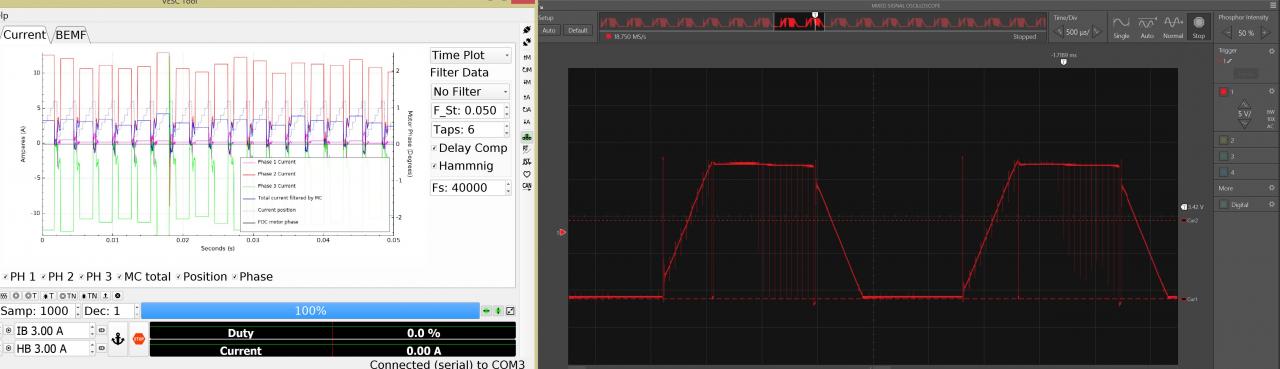
I edited the FW and compiled a 100% throttle limit VESC6. Then I ran a motor at 100% throttle and it seems to run fine. However, the current measurements in VESC-Tool are all wrong. The average current at 100% throttle is very different from the average current at 99% throttle. And the sampled data makes no sense at all. Here on the left is the sampled data. On the right is oscilloscope traces of the phases showing the vesc is indeed running at 100%.
- Is the VESC6 algorithm sampling during the high side switch as it should?
- Is VESC-Tool sampled data only using data sampled during the low side? Why?
- Where is the RT data taken from? It seems like it should be using internal operating variables from the algorithm.
- The green phase 3 plot appears to be the sum of phase 1 and 2, like with a VESC4. I have a VESC6. Why doesn't the tool take the data from the third phase?
I think I answered some of my questions by editing the mcpwm file line 2426:
curr1_sample = duty / 2 + 200; instead of = duty + (top - duty) / 2;
Now the sampled data looks proper when running at 100% throttle. But I still do not see real phase 3 data in the sampled data. The green data still looks like the sum of 1 and 2. I guess this is more of a nitpick but it would be cool to see all three phases.
Following the codes in mc_interface.c file
"
if (mc_interface_get_state() == MC_STATE_DETECTING) {
m_curr0_samples[m_sample_now] = (int16_t)mcpwm_detect_currents[mcpwm_get_comm_step() - 1];
m_curr1_samples[m_sample_now] = (int16_t)mcpwm_detect_currents_diff[mcpwm_get_comm_step() - 1];
m_ph1_samples[m_sample_now] = (int16_t)mcpwm_detect_voltages[0];
m_ph2_samples[m_sample_now] = (int16_t)mcpwm_detect_voltages[1];
m_ph3_samples[m_sample_now] = (int16_t)mcpwm_detect_voltages[2];
} else {
m_curr0_samples[m_sample_now] = ADC_curr_norm_value[0];
m_curr1_samples[m_sample_now] = ADC_curr_norm_value[1];
m_ph1_samples[m_sample_now] = ADC_V_L1 - zero;
m_ph2_samples[m_sample_now] = ADC_V_L2 - zero;
m_ph3_samples[m_sample_now] = ADC_V_L3 - zero;
}
"
There are only two current data (m_curr0_samples,m_curr1_samples) , there is not 3th curr_sample ,so you can not see 3 phase real time current in VESC_TOOL .
-moto_guy