Hi all.
Apologies if this is a known issue or has been talked about before.
Irrelevant background: I'm close to finishing a motor dyno that uses two vescs, and a "dueling motors" setup. I'm using PyVesc to control the two vescs via USB/UART. I've changed the serial format in PyVesc as a few others have had to do to get communication with the latest firmware (https://vesc-project.com/node/281). Two hardware versions: 4.12 (from Ollin), and "6.6" from Flipsky. Currently the test motor is a turnigy sk3 260kv running on the flipsky in FOC, and the brake motor is an align 440kv running on the Ollin on FOC. Both are using 3.40 firmware (VESC_default.bin). They are mechanically linked, so the physical rpm of one is the physical rpm of the other. ERPM is dependent on motor poles of course.
On to the problem.
My code manages to fine tune the brake current on the brake motor reasonably well upto a certain point, then overshoots dramatically. I've witnessed the same thing with direct control in VESC-Toool however, so it's not my code, or PyVesc. I'll demonstrate entirely in VESC-Tool. I'm seeing the same behavior at 500 (real) rpm, and 700 (real) rpm, so i don't think it's a matter of the "coil shorting" mode at lower rpms. Also, i'm getting control over the brake current if i sneak up to around 36.5amps. Once i command past the limit, the measured brake current jumps to ~60a. Interestingly, the limit seems to shift if i don't "sneak up" on the brake current. For instance, if the motors are at a stable rpm , and i command a brake current of 5a, then 5.5a, then 6a, then 6.5a etc up, i can get to ~37a. However, if the motors have a stable set rpm, and i immediately command a braking current of >=22a or so (from 0a before), then i also get to this state with ~60a of braking current.
Any thoughts? It seems like a real bug, not my error, but who knows!
I've tried changing max regen current, power limits. If these were in play, i'd imagine the opposite behavior, where there is a low limit that can't be passed, not a cascade situation. I've also made sure i have somewhere for the regen power to go; a somewhat discharged battery.
I've attached some images of the setup (for context), and of the real time rpm plots during both the "instant brake" mode (image #1) and the "sneak up" mode(image #2). Hopefully you can see the small rpm saw wave looking shape prior to the large drop from the huge jump in brake current in image #2, "sneaking_up_on_brake_current.jpg".
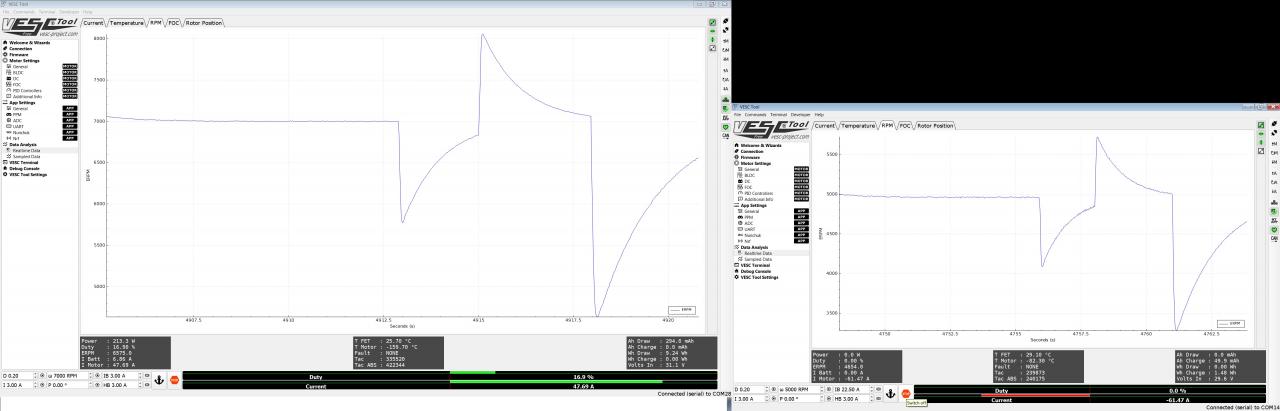

Here is another image of the "sneak mode" inconsistency, this time i'm viewing the current tabs on the realtime charts, which probably gives a cleaner picture of what's happening. Clear stairsteps in current on the right side (brake motor, if it wasn't obvious), then it jumps to -60a or so.
Images and screenshots in full resolution here -> https://drive.google.com/open?id=1SQojjC4ZqsroBtxfL-4DnY8a4JdejJY5
Crazy, right?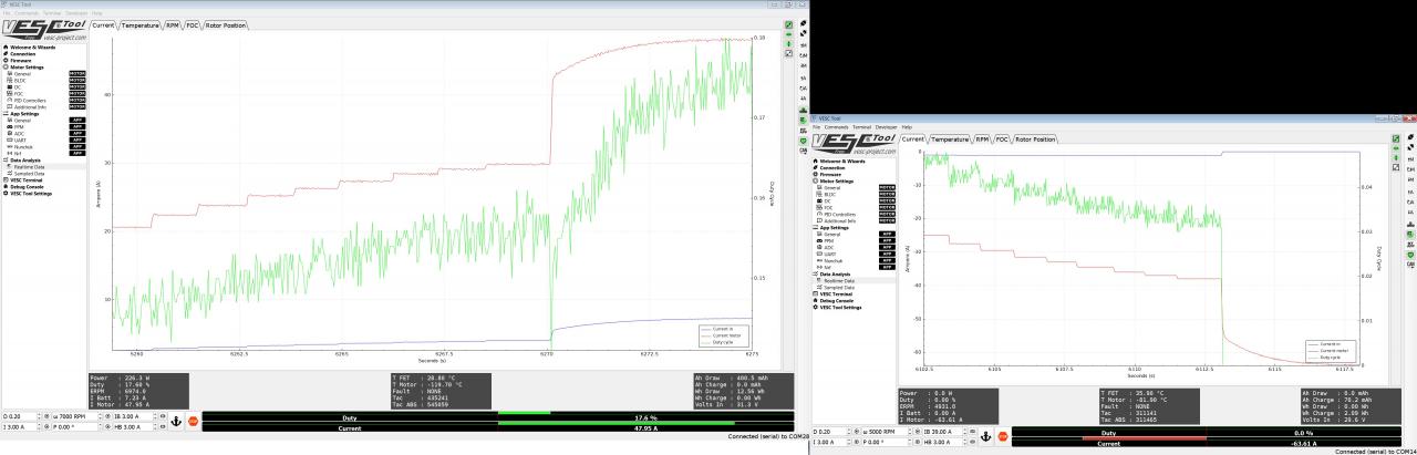
Gosh, i think this is a the same issue @rodread was having with his vesc as a generator. https://vesc-project.com/node/219 and https://vesc-project.com/node/353. I'll do more research and thinking on these posts shortly.
At 0.03 duty cycle, duty cycle is switched to 0.0. Perhaps the line in the firmware that is triggering this is https://github.com/vedderb/bldc/blob/9639780ed414ffa3a795e4896018c76ff9450312/mcpwm_foc.c#L1681, though more research due on that too.
One thing (that's likely really obvious to everyone else), is why a braking load of ~37a and rpm of 700/5000erpm is considered 0.03 duty cycle. Why is duty cycle decreasing as i increase brake current to the motor/generator? If the duty cycle is the % of time the mosfets are open to the battery, wouldn't more braking current require more time and hence a higher duty cycle? Clearly the opposite is occurring. I know at this rpm range, the voltage from the 440kv motor is way below the battery's supply voltage (700rpm/440kv = 1.6V!), so i'm not sure how the battery is getting charged at all, short of some sort of boost converter in the vesc stepping the voltage way up to a battery that's nominally 32v (8s lipo).
If i edit the firmware line and allow a duty cycle lower than 0.03, is there any danger to the controller or battery? Is that the right move? Any thoughts?
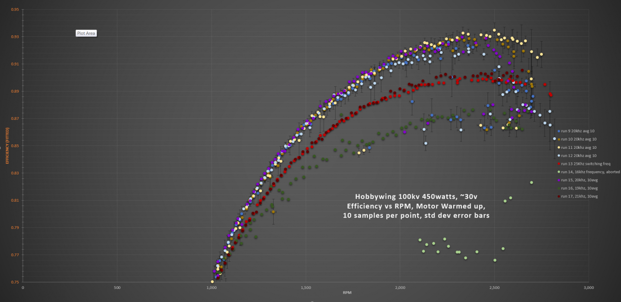
My ultimate goal is to characterize and compare various motors in the 400-500w consumption range, at low-ish speeds, ideally 500-1000rpm, with a supply voltage of 30v. I expect to have to scale the brake motor's kv (by swapping it out) so i don't fry the vesc with overvoltage generated, but also that there is enough braking torque to get to the power range i'm interested in. I've got 60kv, 100kv, 260kv (currently the tested motor) and 440kv (currently the brake motor) motors that are all in the >~2500w rated range, and can all handle at least 10s. I really want good control over the braking load, rather than going with a bank of power resistors.
Thanks in advance!
Peter
This is exactly what is happening. The motor inductance stores energy and the inductive spike that is generated when the MOSFETs are switched is used to push current into the battery.
Look at it this way: the duty cycle determines how "much" of the battery voltage the motor sees. At the same time, the motor is generating its own back-EMF. When the voltage that the motor sees from the battery is lower than the motor's own back-EMF, braking occurs. So to increase brake current, you need to decrease duty cycle.
The problem here - as I understand it - is that the VESC brake mode is designed to stop the motor (and not start to drive it backwards!). So when the duty cycle is low enough, the handbrake mode is activated which shorts the motor (0 % duty cycle / all bottom FETs on). Maybe it would be better to use motor speed as a cut-off instead, and even let duty cycle go negative if needed. (?)
Looking at the comment for the source line you pointed out:
... I'm still not sure why low duty cycle is the problem rather than low back-EMF (i.e. low speed), but one thing is rather obvious: you won't be able to do controlled braking at low motor speed without some kind of position feedback from the motor (hall sensors, encoder, or the like).
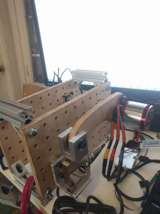
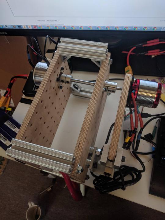
Nice to see your dynamometer by the way!
Thanks arvidb!
I starting thinking about it, researching, and it started becoming obvious what was happening. You're totally right in what is happening, and how we're getting a large voltage to the charge the battery, even at significantly lower rpm than would allow this via the kv rating alone. Voltage surges when no current can flow, then dips once the mosfets open, but the inductance of the windings hold it high while the mosfet is open. Voltage spikes again when it's closed. High voltage inspires the high current we see.
So, in my target rpm and power range, i do need a different brake motor with much lower kv. I think it should still be higher than the test motor, so i don't fry to VESC. If i'm careful to make sure i don't overspeed the generator motor and exceed the vesc's 60v limit, i should be ok. Ps, is this 60v limit absolute, ie momentary, or a sustained limit? Surely the front edge of every voltage spike would/could exceed this limit, is it filtered by a cap or something?
I knew that the generator motor was significantly too high a kv rating, but just didn't expect to see the limitation so quickly. NBD. I could also change the firmware to ignore the 3% limit, but i still don't think i'd get enough. With motor coils shorted together, i'm still only getting 220 watts on the tested motor, and i'm looking for 500.
From a VESC design point of view, it's a bit of a error to assume that the duty cycle indicates motor driven speed. It's a combination of driven speed and braking force. Shouldn't the test be for motor speed? In my case the motor is still going at 700 rpm when the "hand-brake" mode is enabled! Clearly not the situation it was designed for which is braking the last couple mph down to a stop. If you got to 0% duty, you'd never be opening the mosfets to the battery at all. Getting down to 1% isn't much more than the current limit of 3%.
Thanks for the help, i'm getting there, and a brake motor swap is all it'll take to get me where i'm going.
Peter
You're welcome! :)
As for the 60 V limit...
* From the DRV8302 data sheet: "Absolute maximum rating: Supply voltage range including transient (Relative to PGND): -0.3 (min), 70 V (max)".
* From the IRFS7530 data sheet: "Drain-to-Source Breakdown Voltage: min 60 V".
That said, bad things seem to happen at more than 12s Li-Ion (50.4 V fully charged), if you believe lots of the posts on different forums where the VESC is discussed. Probably due to inductance and fast transients? (I have not tested the limits myself, so this is just hearsay.)
I think that if you use the VESC in current control mode (well, any mode except for the braking modes, really) you will find that it operates in all four "quadrants" - that is, it can generate a braking torque all the way to zero speed and "beyond": if you run the motor in one direction, you can set a negative current that will not only brake the motor, but also continue to drive it in the other direction. Close to 0 rpm things get shaky though if you don't have some kind of position sensor.
If I were to use the VESC as a generator, I would write an app that runs on the VESC that controls the motor in current control mode so that current is set to 0 until just below my targeted generator speed, and then decreased quickly (linearly).
In your case, maybe simply set the desired negative current at all speeds above 0. This should give a constant braking torque at all (positive) speeds.
I'm not quite sure what you mean by this
I know you can write custom VESC apps, but i think what you means is what i'm already doing externally from python, see below.
My current algorithm sets the tested motor's speed to something from a list of values, lets its settle, and ramps up the braking current on the generator motor, letting the tested motor settle if it droops too low before applying more brake (so i don't overshoot the braking current significantly, and have to backtrack a lot). Once the tested motor's consumed power and rpm are at the prescribed number and has a small enough variance over the last 10 samples (1 second), record the average of the last 10 samples of load cell's reading, calculating torque, power, and efficiency, then write to a file. Move on to the next rpm in the list.
Perhaps I'll rewrite the code so that it tries to sweep the rpm range at a given power, so i'm not only getting stair-steps of data. If i use the built in power limiting on the test motor vesc, i might be able to do a slow downward sweep with the braking current which allows the test motor to speed up through the interesting range of rpms!
I'll see how good the data looks at the levels i'm interested in, on different motors and make the call to recode it then. I could be smarter about the application of braking current in my present code too. If i make some assumptions about efficiency minimums, i can have a smart start braking current, rather than starting from zero each time. Faster to get to the correct brake current, but has a big hit on rpm. Little time saver, but not much.
It'd be cool to add a matplotlib real time graph to see the test rpm and power settling.
anyhow, i appreciate the help, and think i can get back to it later this week. I'll try to report back with anything more of interest.
Peter
Hi Petertaylor
That's an interesting project. I am also doing something similar.
I have two motors (one I am using as dyno and other as generator) and both are mechanically coupled together. I have a custom build controller running my dyno at desired RPM which I set via UART (LabView application which I wrote). The other 48V motor (which is being used as generator) is attached with a VESC but there isn't any DC source attached with it. I have only connected a load (~6Ohms) on the DC bus.
So far what I have achieved is; when the dyno rotates above 150 RPM I get around 13V on the DC bus which powers up my VESC and current starts flowing through my load resistor (6 Ohms/1000Watts).
I have set Motor Max. current (and motor max brake current) to 60A (-60A) and battery max current (and max regen. current) to 60A (-60A). But my VESC is not braking hard. The maximum I can get is around -2.5A @ 200RPM and ~5A @ 400RPM (the control type I used was 'Current Reverse Center' and 'Duty cycle'). I have tried to use 'Current No Reverse Brake ADC2' but it doesn't do anything. In the VESC tool the CH2 remains grey. I can see its voltage changing when I move my pot. but it doesn't turn green and hence this mode doesn't work.
Can you please share your set-up (both hardware and vesc configuration)? Maybe I am doing something wrong and that is why vesc is not generating more current (that 5A). I would really appreciate a quick reply. Thanks a lot in advance.
SB
SaqibBajwa, perhaps you should start a new thread for your troubleshooting, so more people can see a new topic?
With the vesc tool open, and the test motor running at the 400rpm, what happens when you command a braking current over 5a? On the realtime data area, what does the duty cycle look like when you try this?
Hard to know what's wrong with your setup. Can you post pictures in that new thread? If you show us what you're got, perhaps we can help. I'm by no means an expert, however.
Peter
Hi Peter,
Thanks a lot for your prompt reply. I have started a new thread; https://vesc-project.com/node/615
To answer your question; no matter what break current I set (IB or HB) the regen current (I Batt) doesn't change. It stays the same. Thanks.
SB
For those that might be interested, i've got a few graphs from lotsa runs on a couple motors. Pretty interesting stuff. Just did a switching frequency variation, and it seems like 20khz is honestly preferred by the vesc, and/or this motor.