

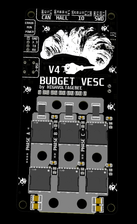
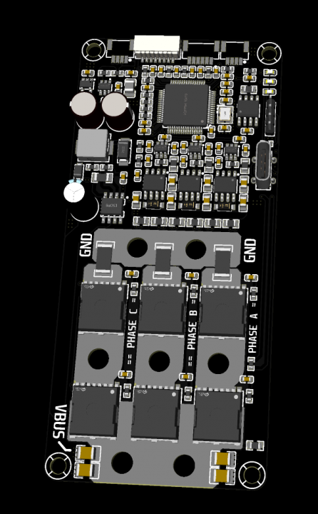
Hello everyone,
I am currently developing a custom VESC-compatible speed controller designed for batterys up to 22S
and phase currents up to 100A
. The hardware design is heavily derived from the Makerbase 75100 (old hardware layout)
, and I have modified the firmware to match my custom pinout and hardware specificities.
The Problem:
The controller operates successfully and spins motors fine when configured in BLDC mode. However, as soon as I attempt to run the FOC Setup Wizard
, the detection process fails completely.
-
Symptom:
The motor does not rotate smoothly; it only vibrates/wiggles violently for a brief moment.
-
Telemetry Data:
During this vibration, the motor current immediately spikes to 100A
in a short burst.
-
Fault Codes:
The VESC Tool log immediately throws either a
FAULT_CODE_ABS_OVER_CURRENTor a
FAULT_CODE_UNDERVOLTAGE.
-
Cross-Testing:
I have tested this behavior with several different brushless motors (including high-inductance hub motors and low-inductance outrunners), but FOC detection fails identically on all of them.
Given that BLDC mode works, the basic phase switching logic seems correct. However, FOC requires highly precise current and voltage feedback. I suspect there might be an issue with my current sensing network, voltage dividers, or MOSFET gate driver layout.
Could there be an obvious hardware flaw in my schematic regarding:
-
Current Sensing / Shunt Amplifiers:
Incorrect filtering (RC network) or amplification gain for FOC to properly sample low currents during low-duty cycles?
-
Deadtime / Gate Drive Layout:
Are there potential ringing issues on the gates that only manifest under FOC's space vector modulation (SVPWM)?
I have attached my schematics. Any insights, layout critiques, or tips on firmware parameter adjustments (like amplifier blanking time or shunt resistance calibration) would be highly appreciated!
Thanks in advance!