Hello
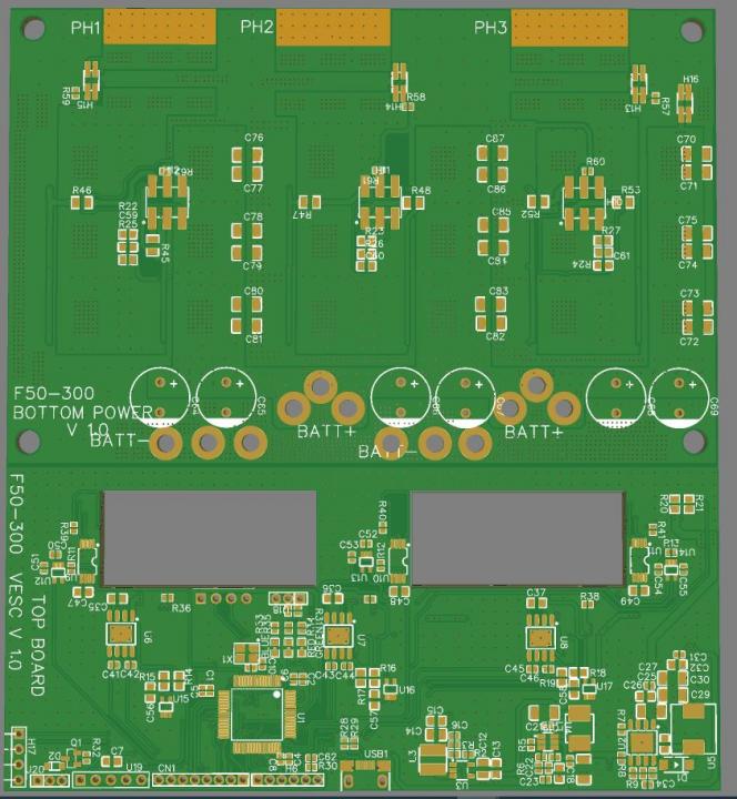
I wanna share my design for VESC controller i made for my diy efoil.
Expected rating 50V 300A not tested yet.
Schematic is copy of 75/300 version but with few components changed.
Mosfet replaced with IPT007N06N, i got them realy cheap.
Rest of the components are more or less the same as 75/300
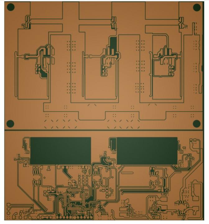
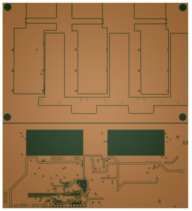
2 boards design top and bottom one are ir same file.
.
A couple of issues that stand out at the first glance. Your battery and phase connections are not balanced. Mosfets closest to output will be overloaded. It's also not clear how you are going to dissipate a lot of heat from mosfets. At 300A or even at 100A, they will desolder and fall off without any heatsink.
NextGen FOC High voltage 144v/34s, 30kw (https://vesc-project.com/node/1477)
Thank you for your answer.
Yes i know hat mosfet closer to output will work a little hader, but i dont think it will be to much problem...
Yes mosfets will be sendwitched between big aluminum hetsink.
As i stated design is not tested yet, will se if it and how it works..
Hello.
I have assembled my controller and im doing some light testing.
Still waiting for thermal pads that i orderd, so i can test it on ful power.
In my light tests i found problem...
Testing setup : Current transformer 120:40mA with 47ohm burden resistor connected to oscilloscope green channel. (oscilloscope setting set to 15mV/A).
In terminal i commanded vesc to run motor foc openloop 120A 3000erpm.
So my question is why im only reading 28.5A in oscilloscope.
Any clue anyone?
Thank you
there is no way each resistor in parallel passes same current with that layout. you can desolder two on each phase or add 6 resistors to average voltage drop on them like this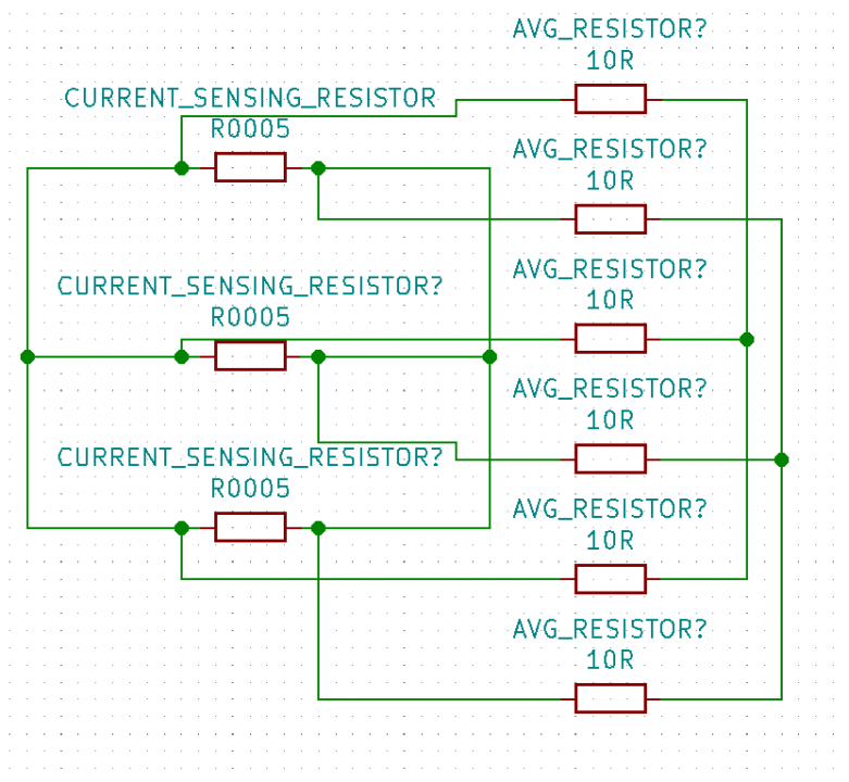
with 2 in parallel it is possible to do it simply on pcb
Yes i am aware of that problem, and placed bus bars across resistor and phase track to battle that design flaw.
And btw, founde my problem..
My oscilloscop probe was connected wrong way.
After i switch polarity, current reading are fine.
Phase currents at 120A 3000erpm.
Both oscilloscope and vesc tool now reads same current.
So allwasy check your connections, guys😄.
I have to remember that my self.