Hi,
We have been using the VESC 75/300 for quite sometime now, but we are having trouble achieving the 300 A continues rating it says it can handle. Attached you may find a graph of real life usage of the VESC on our boat. One can see that after using the VESC puling a motor current of just above 100 A (mean) the maximum MOSFET temperature variable rises almost to 100 ºC (we have limited the temperature to 95 ºC).
My question is, what do we need to do to achieve the claimed 300 A rating? Do we have do a water cooling of the VESC? What have you guys did when you tested the VESC with 300 A?
The VESC is located insid a fiber class box, but this box has a forced air cooling so that the heat can move away from the box.
Hello
waiting for the solution to come from more experienced users than me, I would suggest you to show more information about the setup and how you are using it.
The VESC 75/300 is a really tiny and well made device, but like all controllers in order to be used at the best performance it needs to be closely connected to an excellent heat sink.
http://electricmotorcicles.blogspot.com/
Just attach a large finned heatsink to the 75/300 so the forced air cooling on your box can move more heat away.
It´s possible that your values of detection are not perfect so the motor does not run very efficent. Do a detection on new firmware version, otherwise you have to tweak some values. Try using a lower switching frequency if possible. If you have the chance to use watercooling, just do it. There are some good solutions on efoil builders forum. Watch the 75/300 video of banjamin on youtube, there you can see that he mounted the Vesc on a aluminium plate.
Link to forum post: VESC help offered for private persons and companies
Website: www.electricfox.de
I believe when Benjamin was testing it with a large ducted fan motor at 300A, the controller was attached to a large metal workbench. It seems like to achieve those amps you need to have lots and lots of heatsink mass.
NextGen FOC High voltage 144v/34s, 30kw (https://vesc-project.com/node/1477)
Yes it was clamped to a giant bar of aluminum. The max continuous he got in that test was about 180A. Here is the video if you can't find it. https://www.youtube.com/watch?v=fbK2dcoYS7g
Thanks for all the replies, somehow I have not been notified of them.
- Attaching a large and chunky heat sink is not really a solution for us since wight need to be reduced to the maximum (we are building a solar electric hydrofoil boat).
- Updating the VESC is something that at the moment we didn't want to do because it could break the code we use to control it and we were traveling with the boat in Portugal, but now we are building a new boat and we will try it for sure. Reducing the switching frequency is also something that I only learned recently and we will give it a try..
- Water cooling is something we have also though off, and we want to try it but we would like to machine fins on the aluminum case to have more contact area. Or machine a new case instead. Does anybody knows if case 3D model is available online?
Thanks for the feedback!
I think you will have to use a form of liquid cooling plate to realise the maximum figures over long periods of time. Water transfers heat away from a source upto 1000x more efficiently than air can.
Perhaps a cooling plate with fins actually submerged into the water if location through the hull is possible, then you probably wouldn't need a pump, simply an underwater heatsink.
Hi!
Here is a plot showing the Mosfet-temperature behaviour at 270A phase current for a VESC 75/300 with an aluminium liquid cooling block with good thermal coupling. From my experience the 270A continuous phase current are hard to achieve without overhearting the VESC. With the setup of this test, the default mosfet temperatur limit is reached after 30 seconds.
Best regards
Gerhard
Hi Gerhard,
In your setup what was the maximum continues phase current that you manged to get?
Best regards,
Sebastão
Hi Sebastao,
220A phase continuous without any thermal issues. Value can still be pushed but not tried out so far.
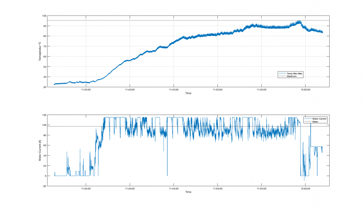
Here you see a phase current and temperature plot of around 200A for about 25 Minutes.
Hi
If you manange to hold the aluminium housing of the VESC cool, try change to the best thermal pad between the mosfet and aluminium housing.
https://www.ebay.com/itm/Gelid-Solutions-GP-Ultimate-120x20x0-5mm-Therma...
You can also find even better with 17W/mk but they are expensive.
And is inportant to have good mounting presure between mosfet and aluminium housing. Is any of the screw a bit lose ? try carfully to tighten them bit.
Hi Markula!
Thank you for the advice. I used thermal glue with 3W/mK with thickness of 0,1mm. So in total 3/0,1 = 30 is my "cooling performance". With this pad from ebay you have 15W/mK with thickness 0,5mm so 15/0,5= 30. There is the same "cooling performance".
To increase cooling performance it is necessary to reduce gap thickness and/or increase thermal conductivity.