After doing a lot of testing trying to figure out what exactly was causing roughness during transition from sensored to sensorless mode, I noticed that currents were not smooth in sensored mode and especially bad during sensorless transition.
There is a clear indication of deadtime distortion happening during transition to sensorless and, in fact, most of the time while running in sensored mode. Motor phase graph was showing bumps and troughs as well. As shown on the pictures below. Once past the transition, the currents and phase line become smooth.
Naturally, I started playing with the deadtime distortion value. It seems like increasing this value helped quite a bit to ease the roughness but I had to bump it to a value just below the point where the motor starts to "misfire" (cogs really violently, due to distortion compensation set too high). So, it had to be very carefully tuned between the least rough transition and the misfire points to find the speet spot.
Another interesting thing I noticed was that the higher I set HW_DEAD_TIME_NSEC in the firmware, the more rough transition was with the default compensation value of 0.12, so I had to bump it up really high to as much as 0.5 to reduce the roughness. However, if I dropped HW_DEAD_TIME_NSEC to ridiculously small values like 260, the transition was smoother and I had to raise the compensation value only to 0.2 or so.
I tested it all on my hardware which uses pretty fast drivers (19ns propagation delay, 100ns HW set minimum deadtime) together with mosfets 90ns (four in one group),12.2mOhm ON gate resistance and 4.4 total OFF resistance. I also checked for this issue on Trampa MK III which uses smaller gate resistance, and the distortion problem is there as well.
Conclusions so far:
1. The sensored mode does not really provide smooth commutation: phase line is never smooth and current show signs of deadtime distortion. The problem gets worse at around transition eRPM. Once past transition, phase and currents look perfect and the motor runs smooth.
2. The deadtime distortion compensation helps to reduce roughness during transition but doesn't completely eliminates it. Running sensorless mode even at very low eRPMs (below 1000) produces clean phase and currents graphs. It feels like sensored mode is just not working well at any eRPM.
Anyone experienced the same and/or have any deeper insights how to best address this issue?
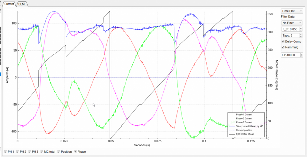
Here is the graph showing what happens during transition. Phase gets pretty choppy and currents show spikes at specific spots pointing to deadtime distortion.
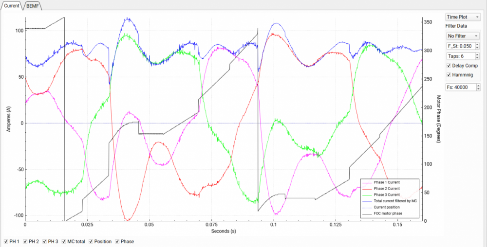
If not cured with deadtime compensation, things can get as bad as this during transition:
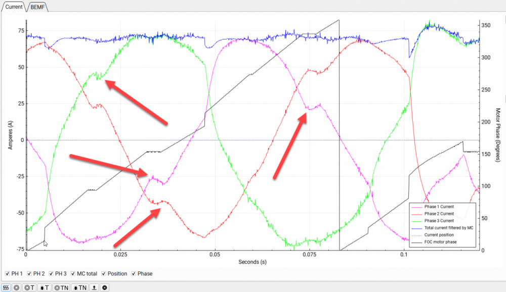
Even before the transition, running sensored mode, the phase and currents are bumpy:
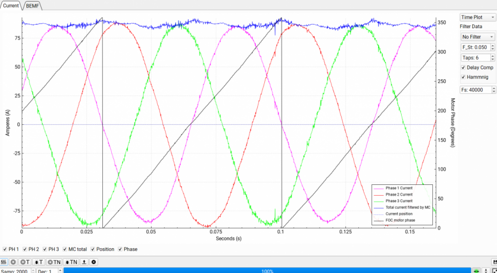
Once past the transition or when running sensorless, all looks perfect:
Looks almost like the sensor positions are not detected correctly there. Given the phase jumps so much with each sensor.
I have found that deadtime distortion setting seems to help more for FOC detection, as it gets the resistance more accurately. Then I set it to 0 when running the motor.
Actually made a mod to the resistance measurement so it sets the deadtime compensation during the measurement step to the set HW_DEAD_TIME_NSEC in the hw config.
Is the transition better at low phase current?
If so, the jumps could be due to the unfortunate combination of two things:
- the first order extrapolator of rotor angle in software is abruptly adjusting at every Hall-signal transition (no-go in FOC!). PLL-like extrapolators are inherently smoother, preventing the abrupt misorientation of field oriented control and should be preferred. It's my personal experience.
- the induction of stator current in the Hall-sensors is not considered in the software. The Halls can't differentiate between rotor ans stator fields. At high phase current, the transition of Halls are not at the same positions as with zero current, as would e.g. an encoder do.
This can be easily compensated by an offset of like atan2(Lq iq, phi_pm + Ld id). The motor parameters are not exactly the same at sensor location though.
When messing around with the deadtime compensation, you modify the way the distortion is acting during commutation, but it is a pure product of Murphy's wishes.
The deadtime compensation should only compensate the deadtime. If you have only 100ns deadtime in HW, I don't see any need for compensation until you switch over 100kHz or have an extremely low motor inductance and resistance.
Yes, all the tests have been done under load and that's when the issue transpires. An unloaded motor starts and runs just fine. I would think sensors provide pretty good tracking of the motor at slow speeds, but that's not the case. The handoff from the censored to the sensorless mode is most vulnerable spot when a momentary loss of torque or cogging tends to occur. It happens on different hardware, so that has to be the software.
NextGen FOC High voltage 144v/34s, 30kw (https://vesc-project.com/node/1477)