Hi Guys
I'm desinging sensored BLDC motor driver. Motor driver voltage 48V, current 20 amp, sensored drive.
Components
Mosfets 75nf75
Gate Driver ucc27211
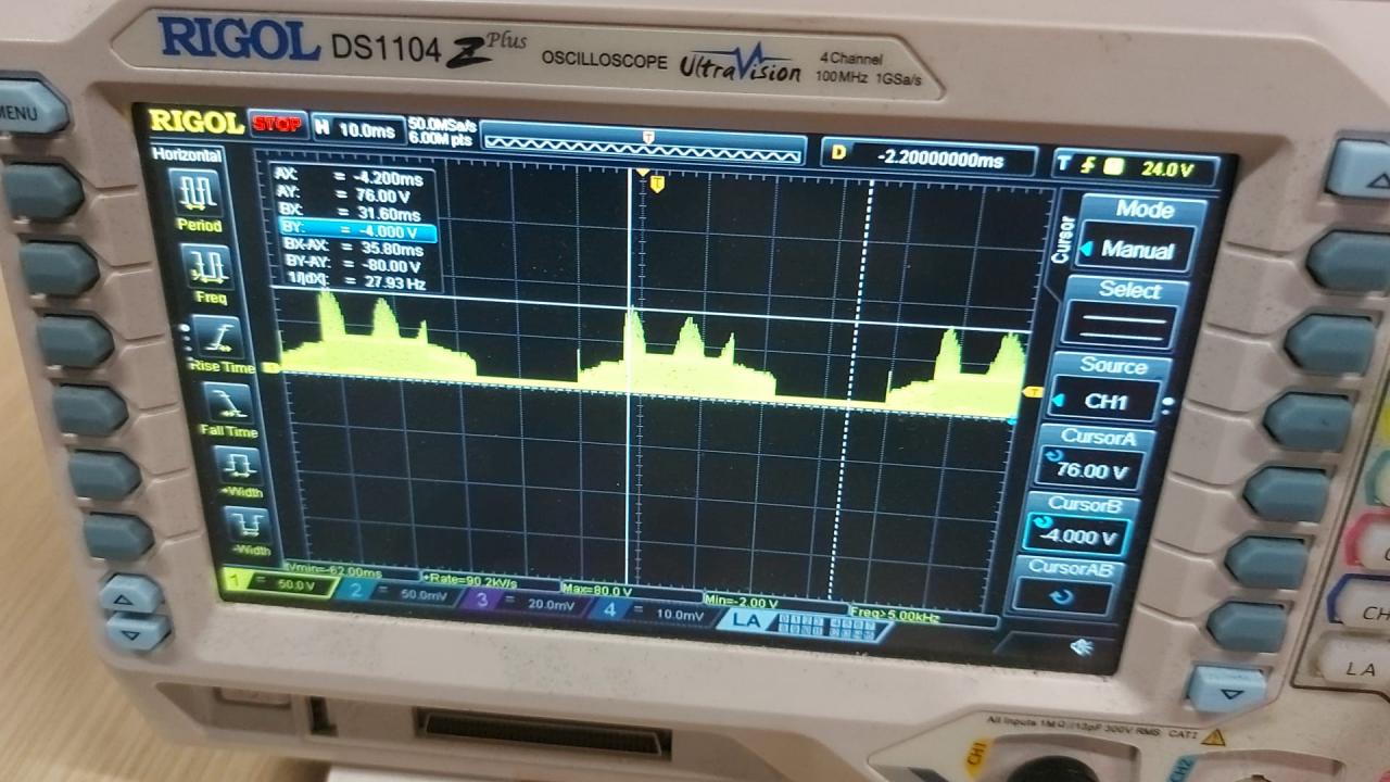
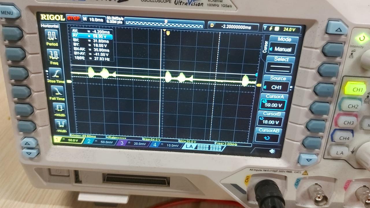
I try to learn from the begining so I don't include current sensing right now. I write some code on STM32F103(Bluepill) for hall effect I use 3 pull up and connect these pins 3 interrupt pin of MCU than set 6 PWM output for the gate driver input. I check PWM signals in logic analyzer and make sure there is no problem on there. I also put 200 ns dead time between complimentery PWM signals.I achive to turn motor but I have some problems. When I check the phase output signal there are too much voltage spike I try to add snubber 1uf 2.2 ohm for all the phase and that didn't work.
I share gerber file and some oscilloscope pictures. Is there any one help me about that.


https://drive.google.com/file/d/1AiGg_tK8OtUrHdmn2MPJsnnn-zw1WzOg/view?u... this is the gerber file of the PCB
https://drive.google.com/file/d/1SViczi1JPsmypAKHFflkHkbTHgSaM-hX/view?u... this is the Schematic of the PCB

it seem to be related with firmware.