Hi all,
just wanted to share some top tips and safety hints with you regarding ESCs with separate logic and power boards such as flipsky 75-200 et al.
While I love the idea of separating logic and power boards for several reasons, you want to make sure, the boards CAN NEVER BE DISCONNECTED DURING USE.
With the mentioned controller, Flipsky 75 200, this has happened to me yesterday. Probably current sense did not work any more and during hall-detection, the ESC probably switched one half-bridge to 100% duty. This resulted in my Battery leads, Motor Leads, complete wiring harness, etc. catching on fire in a few seconds. Fuse could have helped though... ;-)
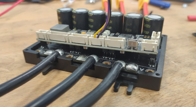
The flipsky controllers have a nice machined aluminium case, but nothing is holding down the top logic board. If you unplug the USB connector you will eventually lift the logic board. It is inevitable.
If you have one of those controllers, you should check RIGHT NOW, if the top logic board is still seated properly AND fix it with some glue/spacer/etc. between the top cover and the logic board.
Also the solder-joints on the headers between logic and power board are shit, so you might want to re-solder those.
Logic board lifted on the side of the USB Connector:
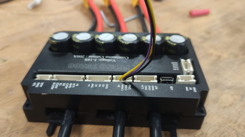
You can also see it from the outside:
Cheers!
This situation is not specific to multi board/modular design. Anything can potentially fall off a PCB, even on a single board, or a wire can de-solder, a connector can be bad, etc. A classic example is losing the ground on the throttle causing uncontrolled acceleration. The best way to prevent fires is to have a properly rated breaker and/or fuse. I have two. One on the battery negative side with the BMS and the other one on the battery positive, just a regular DC breaker. This ensures that if the BMS fails to cut off the overload, the breaker will.
NextGen FOC High voltage 144v/34s, 30kw (https://vesc-project.com/node/1477)
Hello All, I have a similar split design, and I have pull down resistors on the gates of mosfets on power board. I had lots of burnt mosfets before for the same reason.
eguven
This can also happen if the solder joints fail on the connections between the boards. Adding pull down resistors on the power board is a must.
It's quite funny to me that they copied to A200S v2 to make all these boards but didn't include the 2 bolts that hold the boards together to stop exactly this happening :D