I'm trying to make brushless motor controller for my ebike.
I need it to have (forward reverse) (potentiometer input) (maybe brake) (hall inputs)
it's going to be mostly running hall less
Im trying to make it as cheap and simple as possible.
list of components that I have on hand:
smd ceramic capacitors: 50v 1nf 10nf 100nf 1uf 10uf 100uf 100v 48uf
disc ceramic capacitors 50v 106 104
smd resistors: 10 100 1k 10k 100k (2512 shunts) 0.004 0.001
tht resistor kit with values :
1 000 000
680 000
470 000
300 000
220 000
200 000
100 000
68 000
51 000
47 000
20 000
15 000
10 000
6 800
5 100
4 700
3 300
2 200
2 000
1 000
680
510
470
330
270
220
150
100
47
22
10
and a lot of 120
diodes: in5819 uf4007
zener diode kit
current sense amplifier:INA180A3IDBVR
stm32:SMT32G431KBT6
mosfet drivers: irs2186 ucc27211
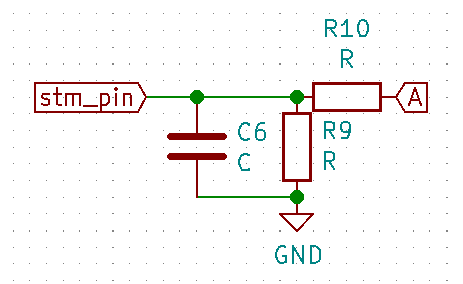
This is phase voltage sense part, what value should I use for these components and do I even need a capacitor there?
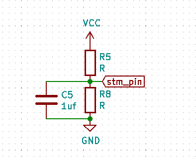
This is input voltage divider
can I connect my hall sensors directly to stm pins? I've seen some schematics with filters and voltage dividers.
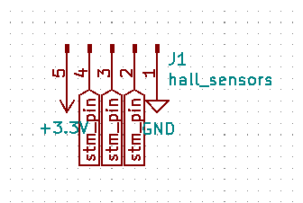
Can I use internal pull up resistors?
is using capacitor C4 good idea and what values of components should I use in this scheamtic
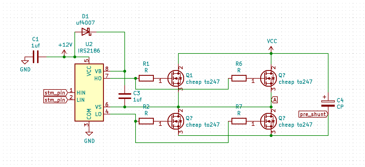
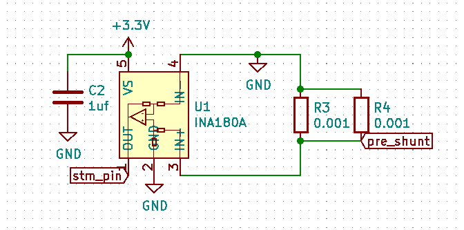
I would prefer to use only one shunt amplifier but if measuring current on each phase individually has some important advantages I can do it.
Again does that schematic look good? Should I use some filters? Different shunt values?
Lastly what stm32 can I use, vesc hardware schematics use STM32F40X_LQFP64 does that mean that I can use any flash size?
Do I need to use 64 pin package?
Is there a list of stm controllers that I could use Or any starting with f40 that has 64 pins will work?
stm32 Software:
Are there vesc software branches?
How do I set up pins, do I need to change some kind of .h configuration file?
Do I need to tell it that it has different than normal resistor values on its phase voltage sense pins?
Is there some kind of pin out diagram?
Are there pin out diagrams for every (supported boards) type that you choose inside conf_general.h?
Should I stick to any of the default board types and base my schematic on that?
Can I simply download zip file from github (without any of this git command line stuff) then somehow compile it and upload it using st-link v2 by using some kind of tool inside cube ide?
Is there some kind of wiki page for vesc with answers for all of these questions? There shoul be since vesc is such a big project right?
To design a VESC for you my hourly rate starts at £1000. However all the information you require is on these forums somewhere.
You can use stm32f407 or stm32f405 without firmware changes. With stm32f446 you need to remap uart in firmware.
Firmware is above 200KB so STM32G431 with 128KB is not enough.
You can use 2 or 3 phase shunts without large firmware changes. I am not aware of implementation with 1 in vesc project.
C4 is for limiting voltage spikes with long battery cables and to stress less battery at low duty cycles which can lead to improved efficiency.
Thanks for replying.
Sorry for not making it clear but I met to ask if I can use one current shunt that would measure power form all phases at once like it is done in cheap brushless motor controllers.
I forgot to ask if I could use internal oscillator? I haven't seen any schematics without external ones.
There is a lot of open source hardware could you recommend one for me to follow with similar characteristics to what im trying to make (200v/100v 80a constant current)?
I know.
There is no guarantee that USB will work with internal oscillator. With 10% variance you could get bad reading of motor parameters.
In my opinion you are searching for cost reduction in wrong places. When I design my priority it's to make it work. Which is hard anyway. And than you can try to improve cost if it's even possible.
look at this forum,there are some with IGBTs
Cheap and high voltage should not be used in the same sentence. At the very least, protect yourself and property by getting a good extinguisher rated for electric fires.
NextGen FOC High voltage 144v/34s, 30kw (https://vesc-project.com/node/1477)
please refer the hardware design of vesc.
some point:
1.you should calculate the voltage divider according to your input voltage, and make sure the voltage to stm32 is under 3v3.
2.whether the hall sensor could connect to stm32 directly depends on the output voltage of the sensor, if the output is under 5V , and then it's ok. If the output type is OD(open drain) or the output voltage is higher than 5V, then you should divide.
3. C4 is needed,and the value of C4 is higher and better.
4. One shunt for FOC is OK, there are ways. While in vesc firmwave, it only support 2 shunts or 3shunts, because using one shunt is much more complex.
5. INA180 is inappropriate. May be INA181 is better, because you need measure current in 2 directions.
6. The shunt value should be small enough, according to your load(80A) and the gain of Amp.
It can be designed according to 100250. Three low side shunts are used. The phase filter can be omitted, and the hardware is also very simple.
Is the 100250 schematic and BOM available somewhere?