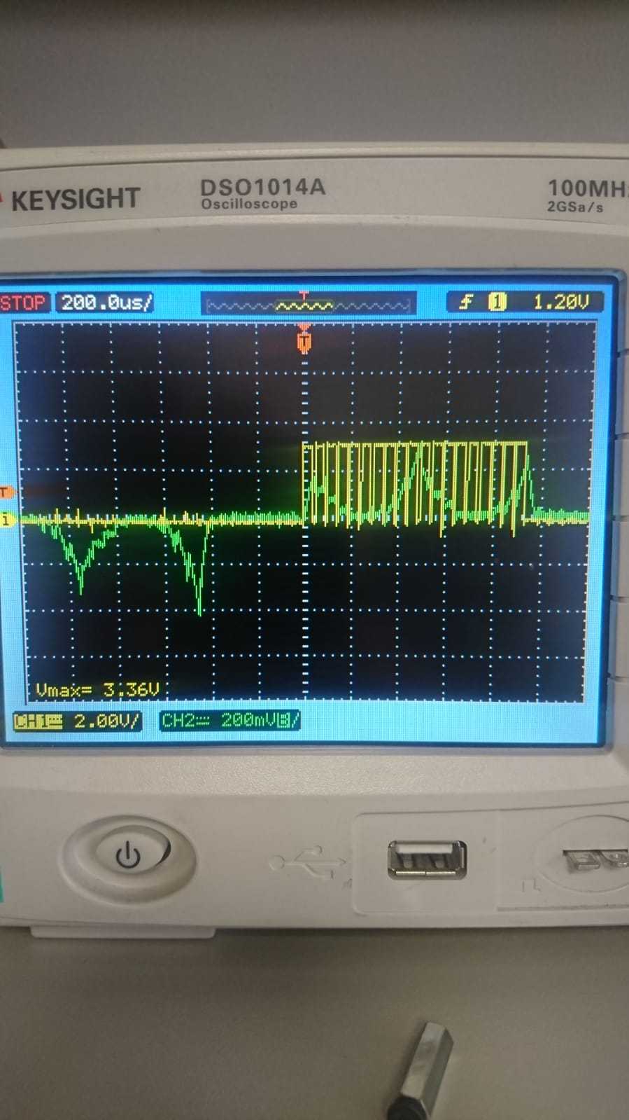
I am working on a BLDC driver project. The motor I have is a 2 pole-pair 12000 rpm motor rated at 1.5kW @57 Volts. I first started with open loop trapezoidal commutation to see motor behavior to implement torque/speed control.control. However the phase current has a weird shape as below

The green shows phase current while yellow channel is pwm signal assoc. to the phase.I inserted a LEM HASS-100 AC/DC current sensor for the measurement. The current peaks reach to 65 Amps (upto 90 amps sometimes) @ 700 watt/12000 rpm.
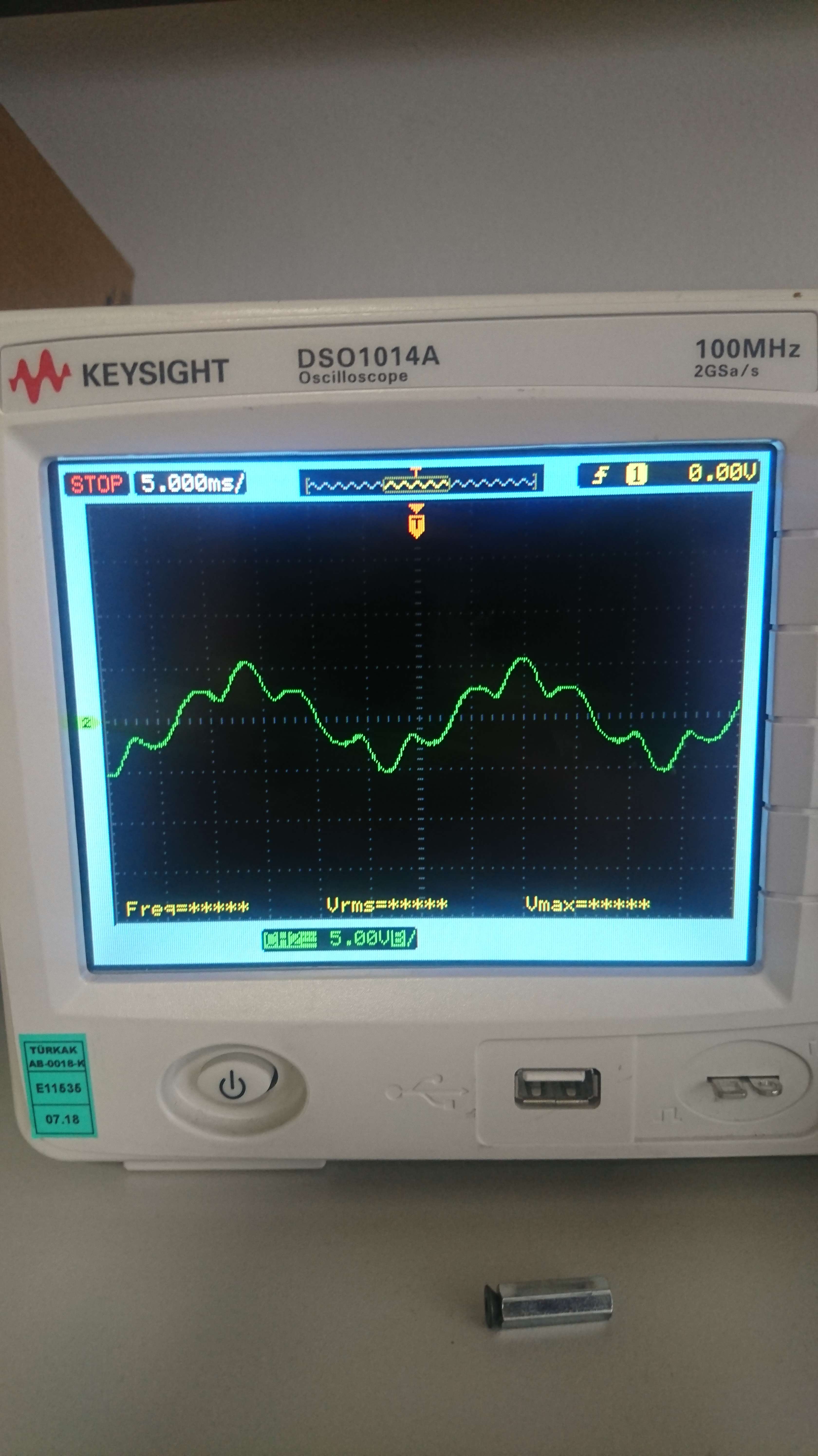
Below is the phase to phase back emf when I turn the motor using a screw-driver.

I have checked hall sensor alignment, all sensors are aligned to 30 degrees wrt to phase back EMF. Can any one comment on the current waveform? How can I control current waveform to make it behave?
