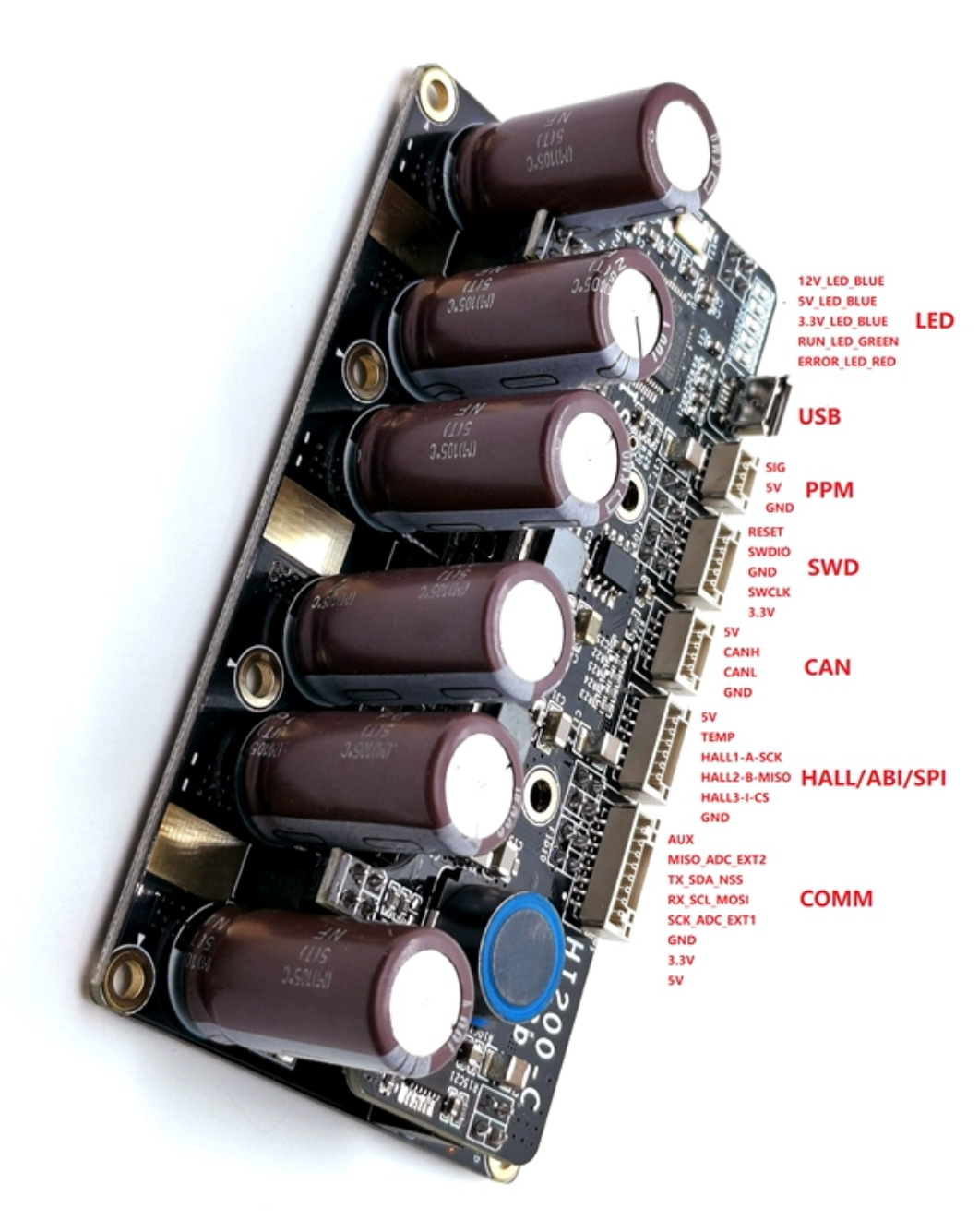
Hello i am completely new to this Forum and also not at all experienced with using VESC´s i have got this 200A 75V Vesc compatible ESC that i need a little help with. I know it is massively overpowered, but i would like to passively cool it, so it should be okay for my application. I want to drive a Sensored Ebike Hub Motor with it and have no idea how to solder the Sensor wires to the strange connectors, that came with the ESC. Also my information is pretty limited, the only things i can give is a Picture from the sellers website, that shows a pinout for all the connectors.

Link to the Seller: Go-FOC HI200/HI100 4-16s 75V 300A electric Surfboard Electric Motorcycle Electric kart bicycle ESC VESC - MakerX (makerx-tech.com)
Link to my Motor:1500W 26” Elektro Ebike Conversion Kit Hinterrad 48V Elektrofahrrad Umbausatz | eBay
As a little extra i also tried to install a Bluetooth module from flipsky to my ESC, but again i ran into problems with the pinout.
Link to my BT Module (Similar to my bt Module): Goolsky FLIPSKY BT Wireless Modul basierend auf dem nrf51 vesc Projekt für VESC4 VESC6 ESC: Amazon.de: Spielzeug
Background information: my Battery is a huge 14S 7P liion Pack with the nice 3350mah(3500mah) sanyo cells installed. As a power throttle i am completely flexible, as long as it fits to my bike and my main priority is just to adapt the strange sensor connector to the ESC´s connector, without breaking anything.
Thanks for your help in advance.
Sincerely Moritz

simply, hall conn;
+5V motor thin red usually
temp may not be available on motor
hallA thin yellow
hallB thin green
hallC thin blue
gnd thin black
comm.;
adc-ext1 throttle green
gnd throttle black
+5V throttle red
+5V bt module Vcc
gnd bt module gnd
rx bt module tx
tx bt module rx
I have the same HI200
Where do i connect a power switch?
When i plug in the battery, it is always on....
Silent Revolution is NOW !
Here you can find my scope output.
There are number of strange things in place
1- All the phases are triggered at the same time. the Ch-1 Ch2 Ch3 of the scope is showing the phase voltages. I broughed them to the same refernce point, then it is obvious that there is a overlap. I would expect there phase shift between them.
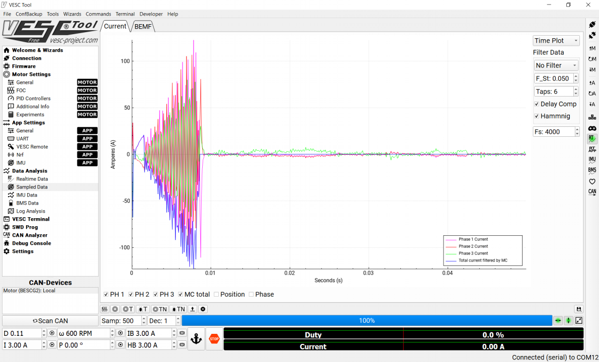
2- I have removed the motor during this test. So the green graph at the bottom Ch-4 is the attached to the shunt on the 1st phase. I can see spikes on the shunt, but the average curent is almost "0" which is expected since there is not load. However when I check the sampled data, as below world of solitaire
I can see current sensing around 100 A. I think the reason is the current spikes occurring on the shunts when the mosfets are switching. One possible solution could be to eliminate those spikes with a low pass filter between the shunt and opamps.
Any recommendantion for the filter to be applied ?
Just to clarify - the Throtylle's positive wire connects to the Comm's VCC (3.3v) port.