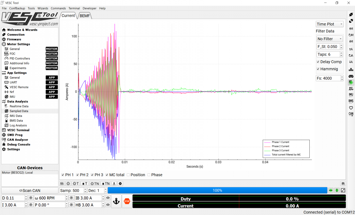
Hi all, we made a pcb, first time it worked great. We added the start circuit and redid a part of the layout and the vesc stopped working. Really strange, but we get a FAULT_CODE_ABS_OVER_CURRENT while doing the Foc setup. Can someone help us with this?

If it worked in the previous layout and the only thing you changed is the layout, then the layout must be the most likely issue. I'd guess noise get injected in current sensing circuit. You can post your FOC graphs when the fault is triggered as well as response from the Faults command in the terminal. That may provide a bit more clue.
NextGen FOC High voltage 144v/34s, 30kw (https://vesc-project.com/node/1477)
Not getting notifications here, but it aint noise we think. Can we maybe video call some time? We did alot of tests the past weeks and nothing solves the issue, made 3 hardware runs, 1st one was good, 2nd was based on the latest schematics, and started resonating, 3th we started from the 1st design with the latest schematics, trying top keep all routing as simular as possible, but again the same issue.
We can show the fault (abs over current) with scope measurements and more of useful, but we cannot get past the Foc calibration, so not sure that to share there?
Hello, I have the same issue. I am using 200u Ohm shunts and INA240 Shunt amplifiers. When the VESC is idle, I see 1.65V at the output of the INA240, which is expected. Vesc interprets this to, a current between -2 /2 Ampere flickering which is acceptible. Once I start the motor, there is a huge spike on the out put of the INA240 measured with scope exceeding 3.3v, and the sampled data reports phase current reaches up 800A ,
I believe I might be missing something on the implementation of INA240, If you share your experiences it would be really appreciated
eguven
Here you can find my scope output.
There are number of strange things in place
1- All the phases are triggered at the same time. the Ch-1 Ch2 Ch3 of the scope is showing the phase voltages. I broughed them to the same refernce point, then it is obvious that there is a overlap. I would expect there phase shift between them.
2- I have removed the motor during this test. So the green graph at the bottom Ch-4 is the attached to the shunt on the 1st phase. I can see spikes on the shunt, but the average curent is almost "0" which is expected since there is not load. However when I check the sampled data, as below
I can see current sensing around 100 A. I think the reason is the current spikes occurring on the shunts when the mosfets are switching. One possible solution could be to eliminate those spikes with a low pass filter between the shunt and opamps.
Any recommendantion for the filter to be applied ?
eguven
eguven
gain of INA240 type?
if input filtering had been applied, r and c values?
It is INA240A1D gain : 20 V/V, there is no input filtering applied. Any recommendation for the filter architecture and R anc C values ?
eguven
r= 2 x 10ohm, c=1.. 10nf
just a look on datasheet
Hakan Seray Şibik from Ankara.
Guys, I have a request from you.I want to contact emrah guven.
If anyone knows the e-mail address, if it can help, I would be grateful. Regards
hakan seray şibik.
seray
seray