Sometimes with higher voltages cross-conduction occurs due to fast rise in drain source voltage driving gate voltage above threshold.
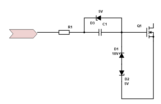
I came with this solution. When 15V driver voltage charges gate to 10V C1 charges to 5V. When driver voltage goes to 0V it should put negative voltage on gate and making it harder to cross-conduct and also make it faster to turn off. For example driver cap will be 1u, C1 100n, gate C 10n.
What do you think? Will it work better than adding capacitor to gate, snubber on output, increasing turn on time? As this shouldn't increase switching looses but lower them. Maybe allowing to use higher switching frequency and thanks to that use less capacitors?
Wouldn't this make the negative bias dependent also on the duty cycle? I've looked into possibly using a small mosfet on the low side gate but it's not as simple as it seems. Looks like a gate driver with Miller clamp would be a preferred reliable solution here.
NextGen FOC High voltage 144v/34s, 30kw (https://vesc-project.com/node/1477)
With 1.5A driver and max duty cycle set to 95% at 20kHz C1 should be providing at least -3,6V(-4V max) to gate turn off. But it's just theory. Benefit would be that it can be used with FD6288 which is smaller and cheaper vs NCV5701A.
On anything above 80v and 200A, I would not use an integrated three phase driver because it's impossible to achieve symmetric routing with good control over parasitic L and C. Integrated drivers with 1A or so are pretty much good for lower power application. For anything targeting above 10kw, I'd use good isolated drivers with low propagation delay and 4/6A source/sink outputs like from Ti. Having a good layout and using proper drivers in the first place may even cancel the need in the Miller clamp.
NextGen FOC High voltage 144v/34s, 30kw (https://vesc-project.com/node/1477)
I want to drive 4x NTMFS5C604NL in parallel. They have very low Vgs(TH)=1.2V so I am not sure how to drive them to not cross conduct.
Is 1EDN7550 in this configuration good for this?
It will be placed directly bellow mosfets to reduce inductance.
On paper, looks like a really good driver. The datasheet says that differential input should "eliminate" false on triggering. Not simply minimize the chance but eliminate. Separate Roff and Kelvin connection should help quite a bit too. I use separate Roff network with diode on a dual channel Ti driver and it helps quite a bit to minimize losses and keep the dead time very minimal. But dedicated Off pin is even better.
The only draw back, kind of, depends on how you look at it, is that it's a single channel. So, ideally, you would need to implement some sort of overlap protection for all three pairs of drivers to have a hardware shoot through protection on top of the software one. This is something that comes standard in dual channel drivers, so you can set your minimum allowed deadtime with a resistor.
I just recently checked waveforms on my latest design and it looks pretty good with Roff set pretty low, almost hard switching off. It works well even with very low dead time settings like 120-200ns.
Here is what it looks like.
Without load, it's pretty nice and clean.
It gets a bit uglier with the load (300A motor) but still not too bad. this is with 10R Ron and 0R Roff. Plus 2R2 on each parallel mosfet for decoupling. By the way, with 4 mosfets in each group, you would need to be extra careful with load sharing. Thinking very effective heatsink that would make sure all mosfets in the group are around the same temperature and some controls over oscillations.
NextGen FOC High voltage 144v/34s, 30kw (https://vesc-project.com/node/1477)