my mosfet setup gate charge is 2x168 uC, and IGBT is 800 uC
both use 4A sink and source drivers. mosfet setup have one 5 ohm resistor for 2 gates, IGBT is slow on 5Ohm, than i tried 0,1 and 2 ohms. on 0 Ohm rise time is similar , but small ringing is present.
Rise time is cca 70ns on both setups.
I managed to get same strange current on mosfet setup, increasing dead time to 500ns.
Playing with dead time on IGBT didn't make a difference.
What is your battery voltage? How did you attached IGBT module to the VESC? Are you using hall sensors?
Motor resistance could be wrong due to IGBT forward voltage drop, error should decrease as battery voltage increase. Current shape looks like ESC is in bldc mode. Will look tomorrow how my currents look on different settings.
Im using UCC27714D drivers, IGBT is all in one device, that have 3x half bridge.IGBT is in EasyPACK package, that just fits in pcb. very easy to connect.
Tried 30v and 60v bench supply.
Tried both hall and sensor less
Mosfet version and IGBT have same schematic, only difference is drivers and transistors.
I suspect on forward voltage drop from IGBT or something is wrong with driving IGBTs.
Do you have a large dc link capacitor connected across the IGBT modules power input? Normally resistance being wrong is because your supply can't actually supply a fast enough current burst, eg if you run on battery you will see different number to a supply limited to say 1A with low capacitance.
Also have you tried adjusting deadtime compensation in advanced section of FOC?
The problem with the resistance measurement and running in FOC is almost certainly due to the IGBT voltage drop. I'm working on an IGBT version myself though, and will add support for voltage drop compensation in the firmware soon.
What type of IGBT are you using? Could be the case that IGBT gate charge is a lot greater than FETS and you are not driving them properly.
Hi,
thanks for response, IGBT is https://hr.mouser.com/ProductDetail/641-FS75R07W2E3_B11A
my mosfet setup gate charge is 2x168 uC, and IGBT is 800 uC
both use 4A sink and source drivers. mosfet setup have one 5 ohm resistor for 2 gates, IGBT is slow on 5Ohm, than i tried 0,1 and 2 ohms. on 0 Ohm rise time is similar , but small ringing is present.
Rise time is cca 70ns on both setups.
I managed to get same strange current on mosfet setup, increasing dead time to 500ns.
Playing with dead time on IGBT didn't make a difference.
btw, rise and fall times was measured on gates.
What is your battery voltage? How did you attached IGBT module to the VESC? Are you using hall sensors?
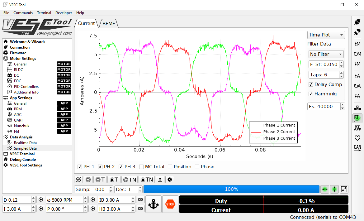
Motor resistance could be wrong due to IGBT forward voltage drop, error should decrease as battery voltage increase. Current shape looks like ESC is in bldc mode. Will look tomorrow how my currents look on different settings.
Hi,
Im using UCC27714D drivers, IGBT is all in one device, that have 3x half bridge.IGBT is in EasyPACK package, that just fits in pcb. very easy to connect.
Tried 30v and 60v bench supply.
Tried both hall and sensor less
Mosfet version and IGBT have same schematic, only difference is drivers and transistors.
I suspect on forward voltage drop from IGBT or something is wrong with driving IGBTs.
Do you have a large dc link capacitor connected across the IGBT modules power input? Normally resistance being wrong is because your supply can't actually supply a fast enough current burst, eg if you run on battery you will see different number to a supply limited to say 1A with low capacitance.
Also have you tried adjusting deadtime compensation in advanced section of FOC?
Hi, dc link is very good, about 4000uF, also have few ceramic. i tried soldering more, but it doesn't help.
changing dead time in source, and compensation in vesc tool, doesn't help either
tried 0 to 6 ohm on gate drivers, same problems.
BLDC mode is working fine ,motor is rotating little bit slower on IGBT than on mosfet version, i suspect that is because of IGBT voltage drop .
The problem with the resistance measurement and running in FOC is almost certainly due to the IGBT voltage drop. I'm working on an IGBT version myself though, and will add support for voltage drop compensation in the firmware soon.
Great to hear that, will test and post results when firmware is available.
thanks.
Resistance measurement my also be off due to the tail current of the IGBTs.