Hi all,
I'm trying to configure braking for use in speed controlled mode. The goal is have the motor control speed by regenerative braking with external force applying torque on the load.
I need to limit the torque applied by the motor, and ideally have the motor coast freely when the speed is lower then preset. I tried to achieve that by setting "Motor Current Max" to zero or other low value, while keeping "Motor Current Max Brake" at nominal value. However I see that lowering "Motor Current Max" also removes the braking capability.
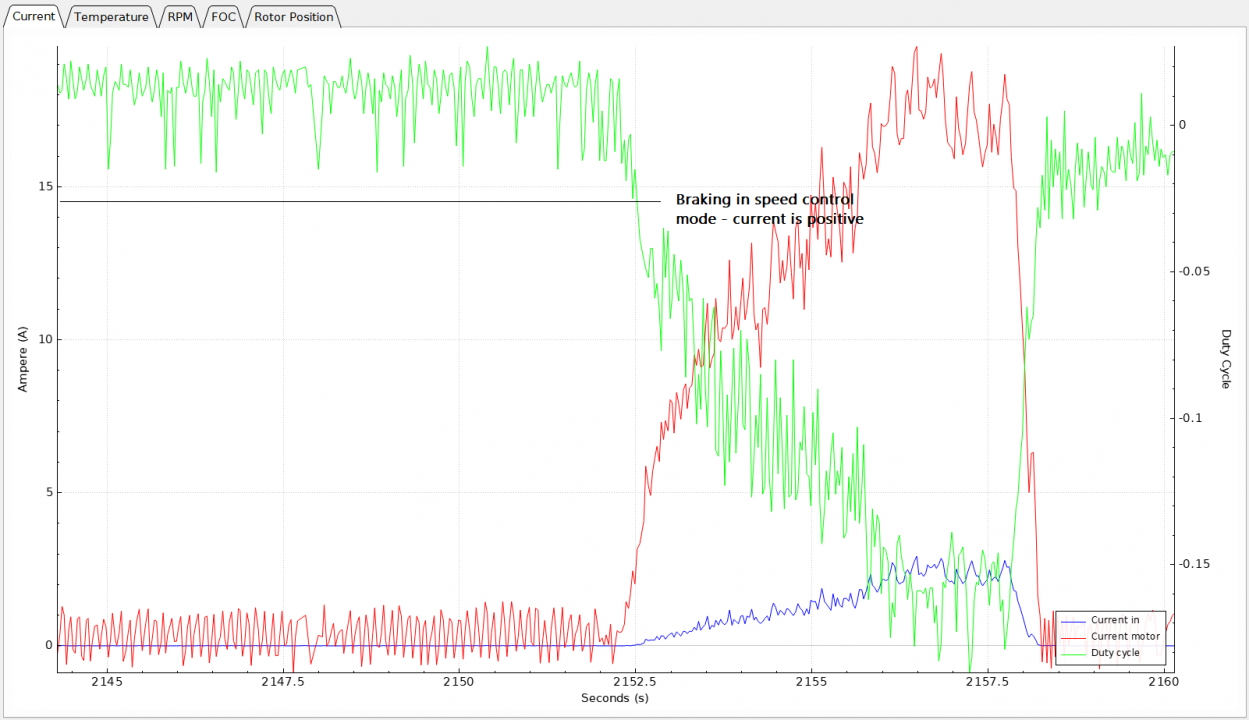
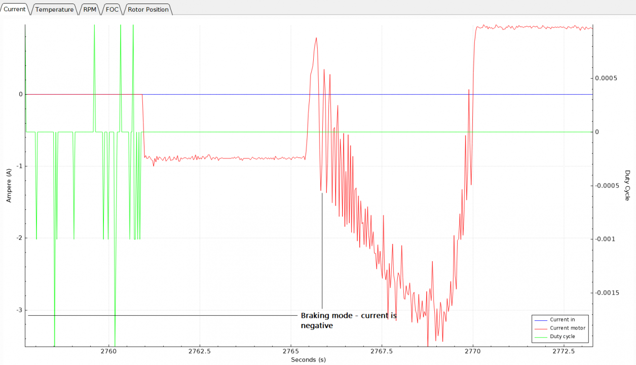
Looking at the current charts, I see that the in speed control mode braking, the current is positive (unlike in braking mode when it is negative, see attached).
So, to summarize :
1. Is braking in speed control mode regenerative (seems like it isn't, by looking the current direction/sign) ?
2. Is there a way to configure coast/brake speed control mode, short of switching to braking mode and implementing external PID control over braking current ?
More test runs in braking mode, more strange results.
1. Brake current limit seems to have no effect
2. Battery current stays zero, whatever motor current is, so no generation happens. And the sign of motor current follows direction of rotation.
(FOC mode, ABI encoder, HW4.10, FW 3.40)
The battery current is not measured directly but calculated as motor current * dutycycle. With the dutycycle being zero, the battery current is calculated as zero.
If you hit "full brake", IIRC, the (lowside) mosfets ar turned on "hard" and remain that way. This way the dutycycle counts as zero and regenerated current is indeed zero. And the sign of the motor current follows the inverse of the running direction.
Thanks, now things make much more sense. This condition in mcpwm_foc.c was clipping duty cycle to zero once it falls below 3%. I've changed the threshold to 0.3% and now I see a battery current and the braking current is controlled.
However there seems to be a bug in subsequent code. Once the threshold activated and the duty is clipped to zero, it never recovers back form the clipping (maybe the clipped value is used in subsequent filter iteration ?)
Edit: yes, when clipping is activated max_duty is set to 0, then inside the control_current() function everything is clipped to 0 too, and zero duty values are fed to the filter forever, until the mode is changed.
// If the duty cycle is less than or equal to the set duty cycle just limit // the modulation and use the maximum allowed current. duty_i_term = 0.0; m_motor_state.max_duty = duty_set;If you can live with a fixed speed setting and a simple linear increase in torque (current) around that speed target, my generator app might be usable for you: https://vesc-project.com/node/618
Thanks, Arvid, looks very useful as a starting point for my own customizations.
Will try to add configuring the settings via UART interface.
Cool!
One thing that you could do as an ugly hack is to modify mc_interface_set_current() in mc_interface.c so that it calls, say, gen_set_current(fabsf(current)) instead of mcpwm_(foc_)set_current(). And of course add a gen_set_current() function to app_generator.c (and its prototype to app_generator.h, which would be included from mc_interface.c). Then you could just send the current setting using the normal motor current commands via UART or VESC_Tool or some external throttle. Of course you won't be able to run the motor normally then, but maybe that's OK?
Anyway, let us know how it goes!
Edit: And of course this "abuse" could be extended to control the generator erpm too - e.g. mc_interface_set_pid_speed() could be modified to call a gen_set_erpm() function instead of mcpwm_(foc_)set_pid_speed()...
I found the terminal interface easier to use from both VESC_Tool and UART. You can follow my progress here: https://github.com/Flytrex/bldc/tree/experiments
By the way, was the linear function intended to track the power curve of internal combustion engine, or simply for easier implementation ?
Thanks for the link - interesting!
The linear increase in brake torque was meant to reduce the risk of oscillations around the target speed (or runaway if the current was set too low) and also to limit jerk, to be nicer to the mechanics in the system. Slamming the brakes is never a nice experience. :)
For this project on the time to certain to controlling of the speed have to keep that one really good and bad too. Braking to having super control on the aussiewritings also have to come from the mood to nominal current work.