Hi,
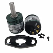
I'm a bit disappointed by the range of motion and feel of the typical e-bike throttles, and I'm wondering if designing my own throttle around these components below wouldn't give me the best results in terms of fine control of acceleration and braking.

I'm planning on using the "Current No Reverse Brake Center". I assume I'll get to read on the ADC pin a signal from 0 to 5V (assuming it is connected on GND, 5V, and ADC1), and in that range I can happily set my center point and tweak the curves as needed. Only uncertainty is around that 5V thing, Is it possible to detect values over 3.3V ? Looks like the software has a max of 3.3V

Right! Max is 3.3V. I use a 4k7 resistor in series from the 0-5V signal and then a 10k resistor to ground.
Thanks Roger.
Does that mean that with those resistor values, the signal is brought back into the 0-3.3V range? Does that also mean that without those resistors, there is a risk of damaging something through excess voltage on ADC1?
Yes. On the STM32 processor family most poins are 5V tolerant. You can drive them with 5V signals. The exceptions are the pins that have analog functions. With a bit of luck you would fry just one pin, but with a bit of BAD luck you'll fry the whole chip. On the other hand, most people can't still use a CPU with a broken pin....
Just for reference: I seem to have made a mistake on my most recent PCB where I needed a 5V analog input signal: I forgot to wire the end of the 10k resistor to ground. So my 5V signal was feeding 5V into the CPU through a 4k7 resistor. My chips (not '405) have survived that. So even though it is beyond spec, feeding 0.36mA into an analog pin does not immediately kill it (or the CPU).