Hi,
We installed my beefed up VESC on the target motor.
First the facts... The motor has a KV of 15. That's 1.5 rad/sec/V and that translates to 0.66 Nm/A. To turn the target motor the torque was measured at 53Nm tops, So..... About 90A should be enough. We set the max current to 120A and... Nothing. We increased the current to 140, 150, 160 and 170A and noticed that smaller currents seemed to work better. As in: when manually controlling the throttle, the motor would suddenly start running and sometimes continue to run. Then with a setting of max 150A stuff exploded. So I hae some rebuilding to do.
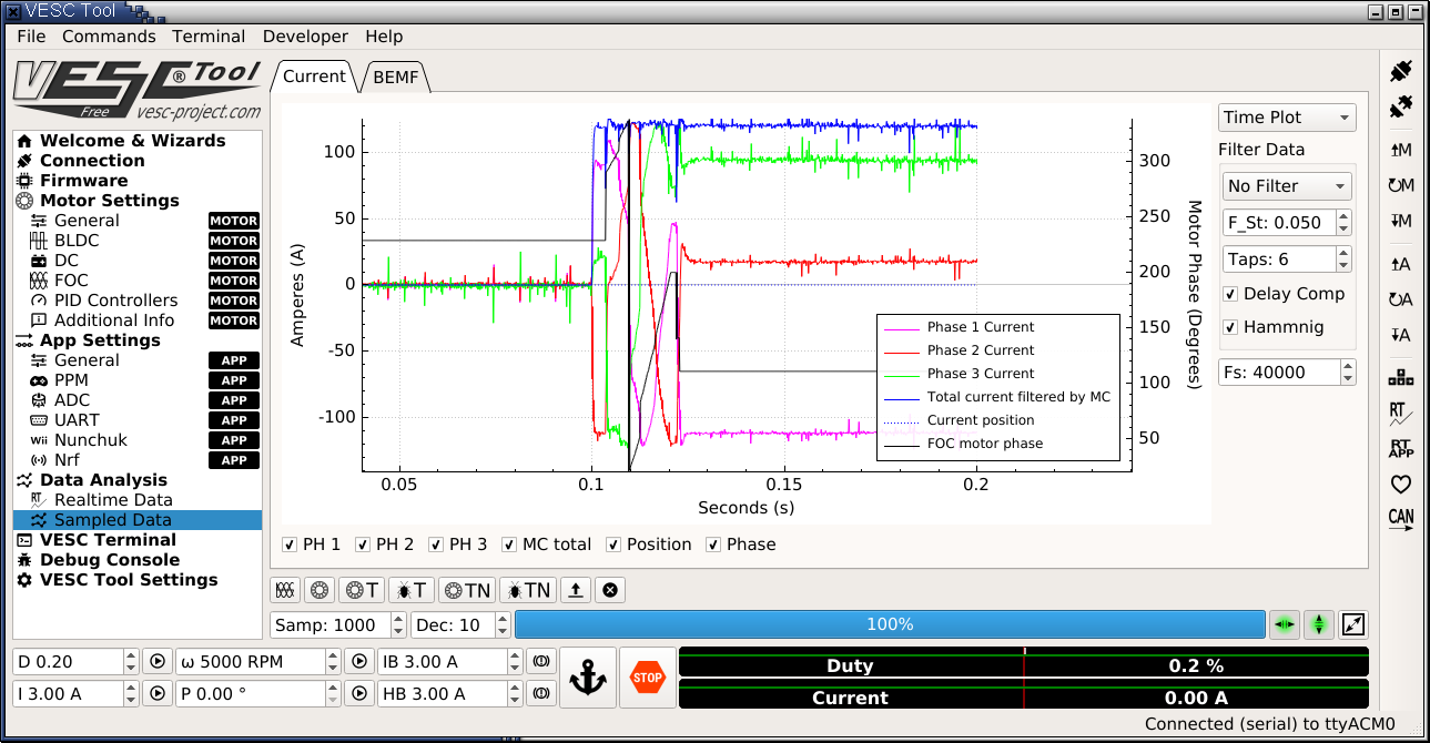
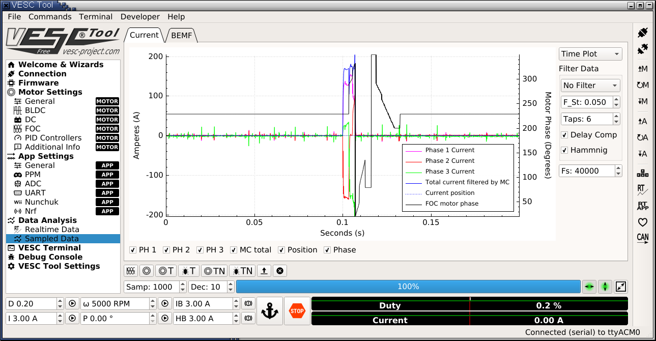
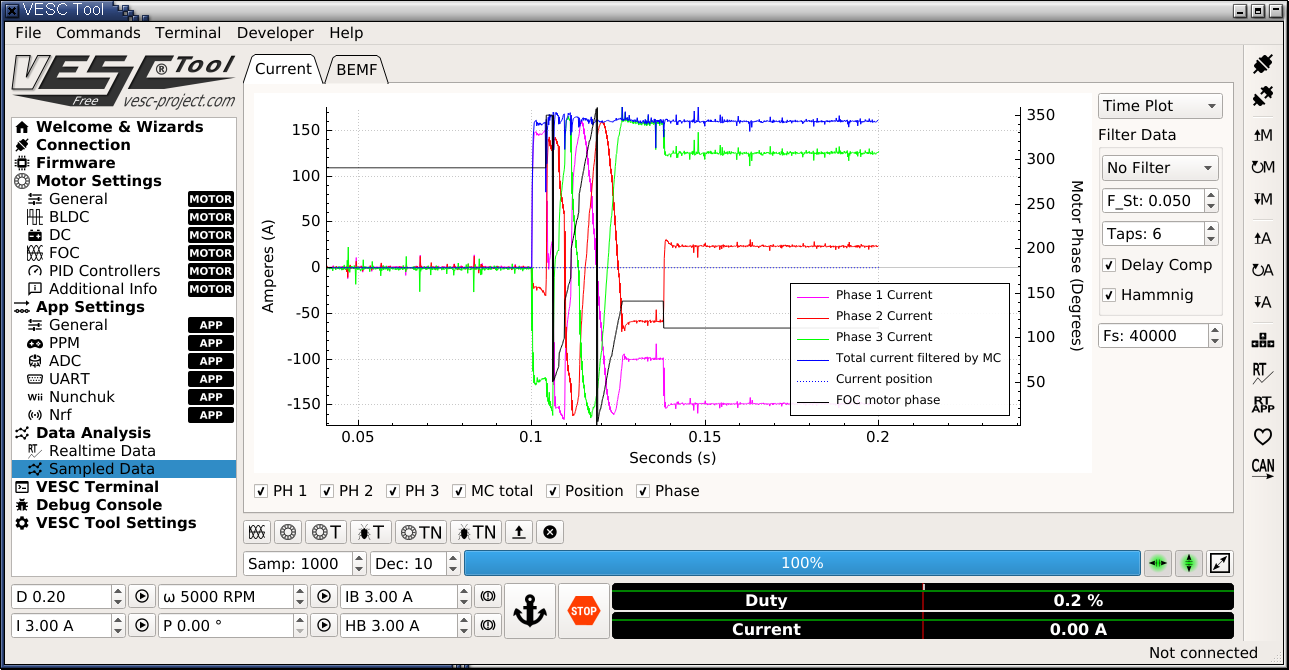
Before things exploded I got the following "when the motor starts" samples.
On each of the three plots you see the following oddities. Or at least I think they are odd...
I told the VESC: sample at motor start, no auto upload. (My computer disconnects while trying to start the motor). (A button I had not noticed before).
1) The current starts being non-zero at 0.1 seconds. Why???
2) It seems the hall sensors force a "backpedal" at some point in time and then things get stuck with quite a large static current running through the motor.
We've been thinking: Could the hall sensors be misplaced? Could the hall table be wrong?
We cannot do "hall detect" on the target motor. It is forbidden to turn that backwards, and it won't turn at less than 50Nm of torque. And the required torque is highly non-linear: it depends on the rotor position. So we're relying on measurements on an identical motor that can turn freely... (and runs fine at 120A and 66Nm of load).
(I tried typing below the images, but apparently that's not allowed.)
The reason that the current starts at 0.1 is that you are using the triggered sampling modes, meaning that sampling is done all the time until the event you are triggering for is found, similar to an oscilloscope. I have used it to figure out what happens before and after fault codes.
It sounds like the hall table or hall sensor placement could be wrong, but I'm not sure. One thing that is concerning is that the USB disconnects, which indicates that the signal integrity is not good. On my first PCBs before the VESC4 I had that problem in addition to my touchpad not working properly with the motor running, but now everything works perfectly even with everything running at full power. On the 75V 18-FET VESC I'm working on I had no disconnects or touchpad problems even when running at 55V and 350A. You should defenitely check the routing on your PCB.
New info.... The motor is identical... but not quite.... The motor frame was measured and rebuilt. That was done perfectly, except that the CAD guy made a mistake with the hall sensors.... The current thinking is that he just mirrored the whole hall sensor so that it would stick out in the other direction (i.e. away from the magnets). The hall sensor holders are mostly cylindrical, so the current thinking is that just inserting them backwards puts them exactly in the spot they should have been, but just the mounting hole is wrong. A new mounting hole was drilled, problem solved....
When you go into precisely one commutation step, so drive A+, B-, and you force the motor through precisely one Electircal revolution, you'll get a sinusoidal like torque curve. When you take say the next commutation step say A+, C-, and do it again, you get a new torque curve, shifted by 60 degrees. For maximum torque you want to chose the activation of the motor that yields the highest torque, i.e. when you plot all those torque curves, you choose the one sticking out above all the others. Now... to make a good choice it helps when the hall sensor state changes exactly when two torque curves cross. Right?
When instead of doing A+B-, like in BLDC mode, you do A+B-C-, like in FOC, wouldn't the torque curves switch by 30 degrees, so that the hall sensors might actually point you in the wrong direction?
As long as the motor turns a little bit, that's not much of a problem: you sync your FOC rotor position on the edges between the hall sensor state changes, but when the rotor gets stuck, you might be 30 degrees down the torque curve when you should be on the next bump, right?
(When I say A+B-C-, this is the phase when A is driven "mostly postive" (almost max excitation) and B and C are driven negative. This varies from C about zero B a lot, through both the same, to C a lot and B almost zero. When B crosses the zero, we go to the next phase, A+B+C-, which starts out with A a lot, B almost zero and moves throug A, B the same to A nearing zero..... )
So there is a new bigger vesc coming ?
I would like to get one as soon as they are available.
C green
How big? I should be able to get you a slightly bigger cannot-be-called-vesc, that can handle slightly higher voltages (but lower currents!).
For the project I'm working on, I would prefer to have the "blows up occasionally" figured out before I start selling them..... :-)
New measurements: I may have mis-treated the current sensors: I replaced the wiring with slightly shorter and neater version.... But I got the pinout wrong. So the current sensors (ACS758) will have been powered from the output pin and stuff like that. Not good. I don't like replacing them: they are soldered to the board quite permanently, and the more expensive sets-of-mosfets as well... So replacing them means replacing the whole power modules. :-(
I'm afraid I'll have to go for that. :-(