Hi, I am trying to find the hall sensors filters on this VESC flier model. I will Use encoders and would need to remove them. Looking at the board schematic on github I cant get may head around this board.
So after looking at the board and the cables coming from the motor (hall sensor today) more carefully. I might have figured it out. What do you think about this schematic?
Trying to detect the AS5048 encoder, BLDC-Tool shutdown after Segmentation fault (core dumped) and the VESC i blinking red 3 times (looks like it restarts).
So can someone tell give me helo/guidelines on what could be wrong:)
Here is the steps I did so far:
So I went ahead removing what I think is R11-R13
Did a solder Jumper on R8-R10. (I see I did a typo on R8 next to R11, it should be R10).
3D printed a encoder mount for the Dev board and a magnet bracket for the motor.
I solder some pins to the encoder
I did the following connection on the AS5048
SCL/SCK -> HALL 1
A2/MISO -> HALL 2
A1/MOSI -> VCC
SDA/CSn -> HALL 3
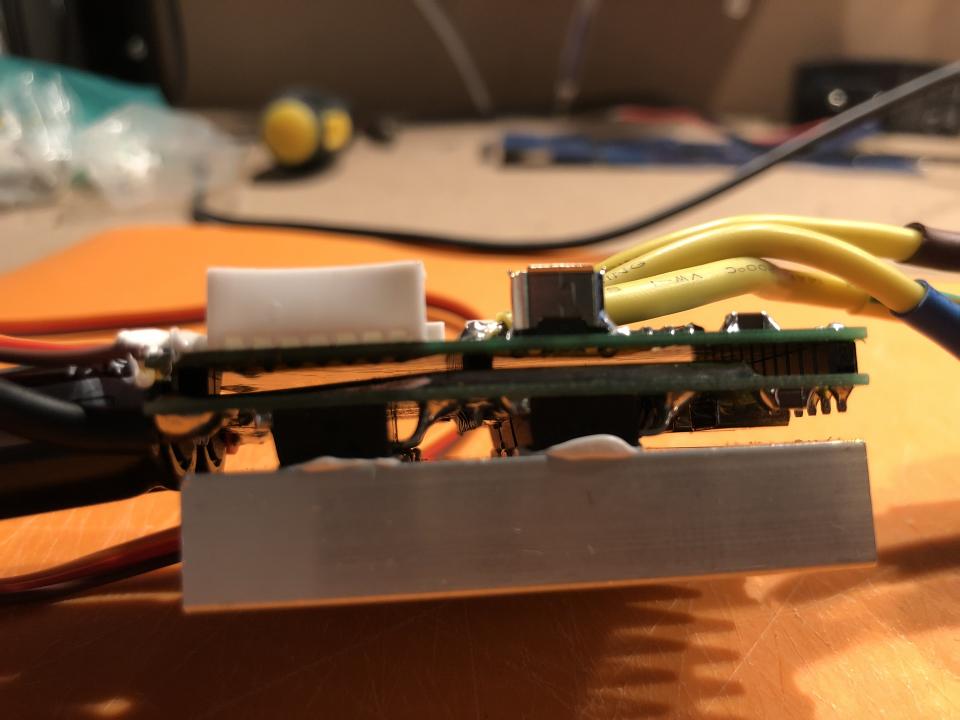
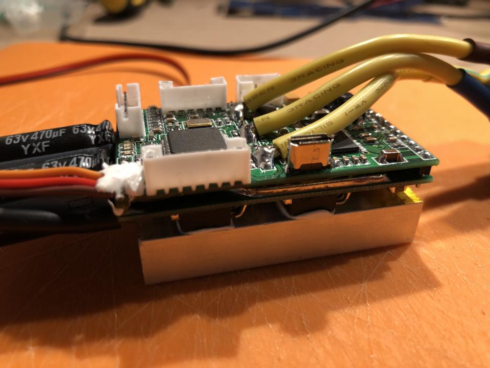
The setup (I did not have any shielded cables at home)
Stupid me, I forgot ro remove C5-C7. :-) Anyways looking better now. But It stills looks a bit messy. The Encoder is moving very much even when its not moving.
So, I made a shielded cable an the encoder works better. But I only get encoder degrees between 180-360.
I read on the vedder forum:
I think the AS5047 support uses a software SPI, in encoder.c :
The MISO ReadPad is done after the SCK SetPad, when it probably should only occur after the SCK ClearPad
How can I edit the encoder.c to test if this work?
Just tested an AS5048D and same problem here. Could only get position at 180-360 degrees over SPI. Connected it over ABI and it worked like a charm 0-360. Why is SPI giving me this problem? I will test an AS5047P next week to see if I have same problem there. Would be great if someone could help me with the 180-360 degrees over SPI problem.
Note: I tested to compile the latest BLDC firmware and edit the encoder.c The MISO ReadPad is done after the SCK SetPad, when it probably should only occur after the SCK ClearPad
The AS5047P is arriving today, I will give that a try with SPI later tonight. I tried the AS5047D @SPI and same problem there, only reads 180-360.
But I guess I can run the AS5047P @ABI if I can not get the SPI working. Or is there any disadvantage with this?
I also have the amt102v but that does not fit witihin this build ;-)
The disadvantage of the ABI mode is that it only gives a valid angle after detecting the index pulse. In SPI mode a valid angle is provided from the start.
And now I can read position between 0-360 degrees with the AS5048A, But I still have some noise problems I need to deal with. What´s the diffrents to ignore the MSB and use 13 bits instead of 14?
The detection result sounds reasonable. I'm not sure what the problem is, and in fact I'm not sure why you need the change to the code in the first place. Are you running the encoder on 5V or 3.3V? I had most success running it on 3.3v supply and io, on 5V it did not really work for me. Also, make sure that one mechanical revolution corresponds to 0 - 360 degrees.
@benjamin The AS5048A is up and running good now and readings postions 0-360. I enabled the HW pins and change the encoder.c with the following. I am also running the encoder with 3V instead of 5V.
Friday fun!
Testing the AS5048A encoder with the temporary drive system. Motor brackets are still 3D printed and not perfect (waiting for CNC Milling), therefore some annoying noises! Running VESC FOC Mode @10% Duty.
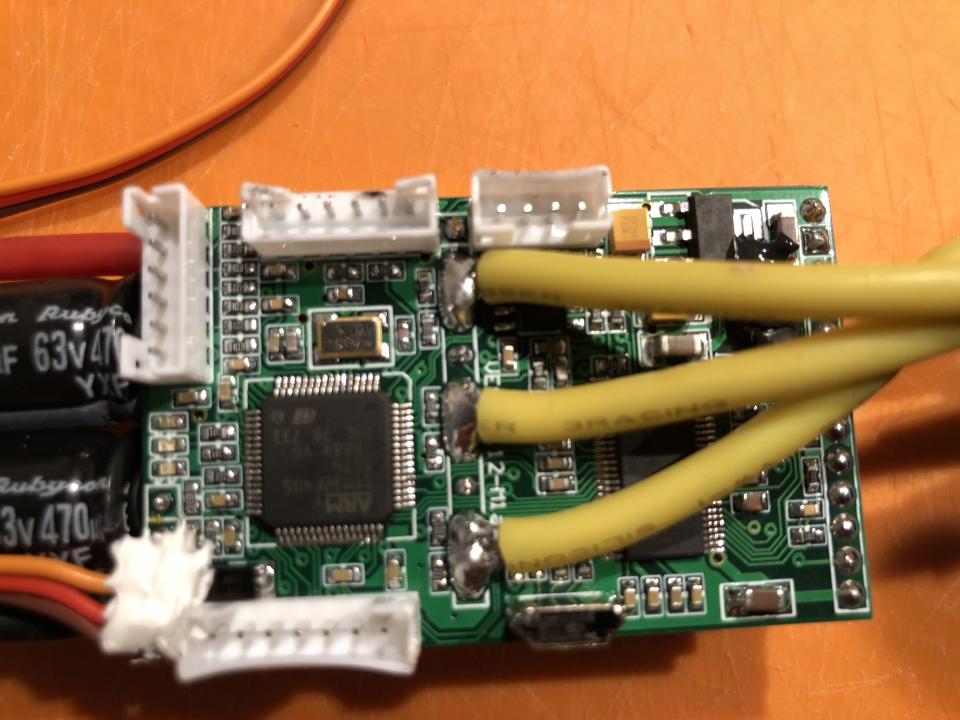
So Could it be this ones? If that´s the case how can I know which ones are R11-R13 and R8-R10?
Follow the construction of the 3D Printed Jetson TX2 based Valify robotic lawnmower build
So after looking at the board and the cables coming from the motor (hall sensor today) more carefully. I might have figured it out. What do you think about this schematic?
Follow the construction of the 3D Printed Jetson TX2 based Valify robotic lawnmower build
Trying to detect the AS5048 encoder, BLDC-Tool shutdown after Segmentation fault (core dumped) and the VESC i blinking red 3 times (looks like it restarts).
So can someone tell give me helo/guidelines on what could be wrong:)
Here is the steps I did so far:
So I went ahead removing what I think is R11-R13
Did a solder Jumper on R8-R10. (I see I did a typo on R8 next to R11, it should be R10).
3D printed a encoder mount for the Dev board and a magnet bracket for the motor.
I solder some pins to the encoder
I did the following connection on the AS5048
The setup (I did not have any shielded cables at home)
Video of encoder detection:
https://www.youtube.com/watch?v=QDKqAUgTmDc
Follow the construction of the 3D Printed Jetson TX2 based Valify robotic lawnmower build
So the work continues.
Now when I run the encoder detection I can see something happens on the Rotor position tab. But Not very stable: see video:
https://www.youtube.com/watch?v=Yw0lMJBFZ24
I connected the AS5048 as below:
Follow the construction of the 3D Printed Jetson TX2 based Valify robotic lawnmower build
Stupid me, I forgot ro remove C5-C7. :-) Anyways looking better now. But It stills looks a bit messy. The Encoder is moving very much even when its not moving.
Video https://www.youtube.com/watch?v=R189nbmtxeU
Is this because of the cables?
Follow the construction of the 3D Printed Jetson TX2 based Valify robotic lawnmower build
So, I made a shielded cable an the encoder works better. But I only get encoder degrees between 180-360.
I read on the vedder forum:
I think the AS5047 support uses a software SPI, in encoder.c :
The MISO ReadPad is done after the SCK SetPad, when it probably should only occur after the SCK ClearPad
How can I edit the encoder.c to test if this work?
Follow the construction of the 3D Printed Jetson TX2 based Valify robotic lawnmower build
Just tested an AS5048D and same problem here. Could only get position at 180-360 degrees over SPI. Connected it over ABI and it worked like a charm 0-360. Why is SPI giving me this problem? I will test an AS5047P next week to see if I have same problem there. Would be great if someone could help me with the 180-360 degrees over SPI problem.
Note: I tested to compile the latest BLDC firmware and edit the encoder.c
The MISO ReadPad is done after the SCK SetPad, when it probably should only occur after the SCK ClearPad
But that did not work!
Follow the construction of the 3D Printed Jetson TX2 based Valify robotic lawnmower build
Nice project, I also have a custom lawn mower in the plans some time in the future :-)
I will order an AS5048 and give it a try myself, it should be possible to get it running. Did you have a chance to test it with the AS5047 and SPI?
Thanks benjamin :-)
The AS5047P is arriving today, I will give that a try with SPI later tonight. I tried the AS5047D @SPI and same problem there, only reads 180-360.
But I guess I can run the AS5047P @ABI if I can not get the SPI working. Or is there any disadvantage with this?
I also have the amt102v but that does not fit witihin this build ;-)
Follow the construction of the 3D Printed Jetson TX2 based Valify robotic lawnmower build
The disadvantage of the ABI mode is that it only gives a valid angle after detecting the index pulse. In SPI mode a valid angle is provided from the start.
Thanks Benji,
I compiled the FW with your suggested example:
void encoder_tim_isr(void) {
uint16_t pos; spi_begin();
spi_transfer(&pos, 0, 1);
spi_end();

pos &= 0x1FFF;
last_enc_angle = ((float)pos * 360.0) / 8192.0; }
And now I can read position between 0-360 degrees with the AS5048A, But I still have some noise problems I need to deal with. What´s the diffrents to ignore the MSB and use 13 bits instead of 14?
I will also try the AS5047D & the AS5047P. :-)
Many thanks!
Follow the construction of the 3D Printed Jetson TX2 based Valify robotic lawnmower build
So after some rewiring the AS5048A is working without to much noise.
But when I try to run the motor with encoder in FOC mode it just gives funny noises or behaves very strange.
steps:
Encoder detection: Gives me Encoder Offset: 280,60 and Encoder Ratio:7,00
Anyone got tips on this?
Please see below settings:
Follow the construction of the 3D Printed Jetson TX2 based Valify robotic lawnmower build
The detection result sounds reasonable. I'm not sure what the problem is, and in fact I'm not sure why you need the change to the code in the first place. Are you running the encoder on 5V or 3.3V? I had most success running it on 3.3v supply and io, on 5V it did not really work for me. Also, make sure that one mechanical revolution corresponds to 0 - 360 degrees.
Okej. So when using 13bits I get a maximum resoultion of 8192 cpr? Instead of 16384 cpr?
I did try some more yesterday night and it seems to be an alignment issue.
I also read one can use the HW pins for the encoder by enable them in the FW. Could this be something to try in order to get SPI and 14bits running?
I am running with 5V from the hall sensor port. I saw that a 3V pin is a available on the HW pins.
Should I give the HW pins a try?
Follow the construction of the 3D Printed Jetson TX2 based Valify robotic lawnmower build
@benjamin The AS5048A is up and running good now and readings postions 0-360. I enabled the HW pins and change the encoder.c with the following. I am also running the encoder with 3V instead of 5V.
/**
* Timer interrupt
*/
void encoder_tim_isr(void) {
uint16_t pos;

 spi_begin();
spi_transfer(&pos, 0, 1);
spi_end();

 pos &= 0x3FFF;

 // Handle encoder rollover up or down.
if(last_encoder_counts < (16384 / 4) && pos > (3 * 16384 / 4))
{
  cumulative_encoder_counts -= 16384;
} else
if(last_encoder_counts > (3 * 16384 / 4) && pos < (16384 / 4))
{
  cumulative_encoder_counts += 16384;
}

  // Now account for actual reading changes
cumulative_encoder_counts += (pos - last_encoder_counts);
last_encoder_counts = pos;

 last_enc_angle = ((float)pos * 360.0) / 16384.0;
}
The mode was found at https://github.com/tlalexander/bldc
Thanks for the help once again.
Follow the construction of the 3D Printed Jetson TX2 based Valify robotic lawnmower build
Friday fun!
Testing the AS5048A encoder with the temporary drive system. Motor brackets are still 3D printed and not perfect (waiting for CNC Milling), therefore some annoying noises! Running VESC FOC Mode @10% Duty.
https://www.youtube.com/watch?v=h7JsRsa5fl8
Follow the construction of the 3D Printed Jetson TX2 based Valify robotic lawnmower build
New AS5048A encoder mount. HE-14 header fits great and I installed pull relief for the cables on the back.
Follow the construction of the 3D Printed Jetson TX2 based Valify robotic lawnmower build