Hi All,
im a passionate ebike builder and i have been always looking for a robust ESC with high current capability. I came across the VESC 4.12 and was very impressed by the opportunities it offers. Sadly i managed to blow 4 DRV's and got tired to repair them. I came across this VESC based ESC from the Netherlands :
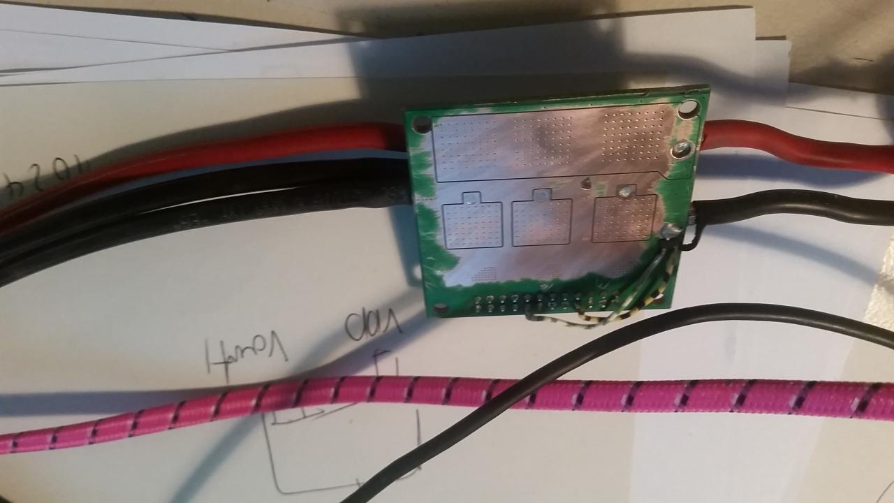
It has no DRV so you cannot fry it. It is programed with the VESC TOOL which makes it as user friendly as the VESC i used . It has no cooling when you buy it but thats what the description tells you. You have to do sth on your own. I tried to cool the fets with minimal space and weight requirements. I wanted an optimal heat flow from the fet tab to a small cooler which is therefore directly soldered to the backside of the power board. Then a forced air cooling is applied to remove the heat.
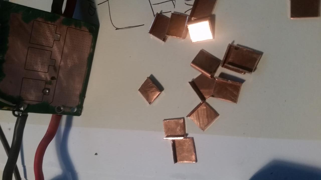
I removed the coating to on the backside of the power board with a dremel:
then i made small angled copper tabs :
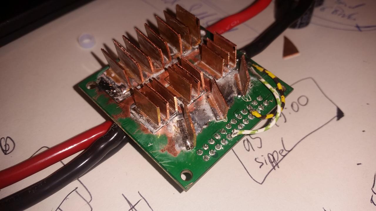
 Those are then directly soldered to the backside of the power board with a powerful soldering iron ( Weller W201C) . Care must been taken to avoid shorts between the tracks!
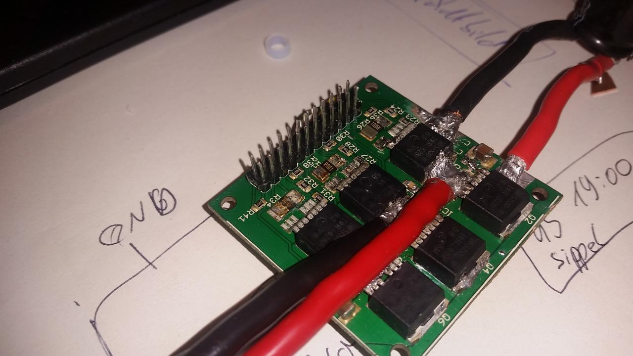
 the other side of the Power board:
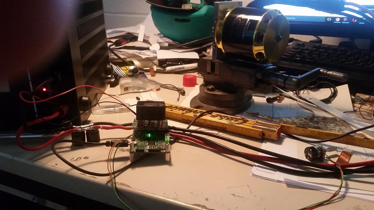
 The backside of the power board is cooled with an airflow ( The BESC has a 12 V output which can be used for this, i used the power supply in this case )
 The result is a steady state temperature of 42°C at 100A phase current. As a load i used a scorpion HK 7050 Motor in foc open loop - as demonstrated by benjamin vedder . To me it is a very astounding result to get a 6 fet controller that gentle to 100A current continuous!. -Therefore i want to share my results with this cooling mod.
Philipp
Nice!
Note that the board (and the fets) is designed to be cooled from THIS side. So without the mod, you have a flat surface to mount against a heatsink (through a silicone insulator). You probably won't achieve 100A, but at least you're a bit better off than "about 50A" that you get with "reasonable airflow around the module".
Next time... you can consider rotating the tabs that you soldered to the power bars by 90 degrees... Then the tabs will help even more to carry the current across the PCB. The thing is... The "rule-of-thumb" for current in PCB wires is: 1mm per A of current. So with 100A, we would need a 100mm wide track to carry the current from the power connector to the FETs... I did order "double the copper thickness, but you can still see that 50mm is simply not going to happen. So anything that you can do to help performance in that area will actually be beneficial.
(The "top" row of tabs is on "VMOT", the battery +. The next row is on the motor phases, and the next row of "just three tabs" is there to cool the current shunt resistors. Those also need cooling: They are loaded to the motor current at 50% dutycycle, so about 5W at 100A motor current. The resistors are officially rated for 2W, so you're pushing the limit a bit....)
Thanks! I know from experience that these shunts can unsolder and are then pushed away from the PCB by Lorentz force (and then make a short to the main board and killing the gate driver...). Therefore i put three extra tabs to cool also the shunts as you recognized. next thing will be to build a housing . I'll let you know
Oh, yes, shunts desoldering and finding them elsewhere sometimes happens if you do foolish stuff. :-)