Hello,
we are currently testing a slightly modified version of BESC G2.
While testing, we faced a strange behavior. Under certain conditions, the PWM input signals of the gate drivers gets some kind of "unstable". In detail, the duty cycle is suddenly incorrect (too long) for individual pulses.
The circumstances under which this happens:
- Voltage >= 60 V
- Metal surface near PCB covering area of STM32, gate drivers and MOSFETs
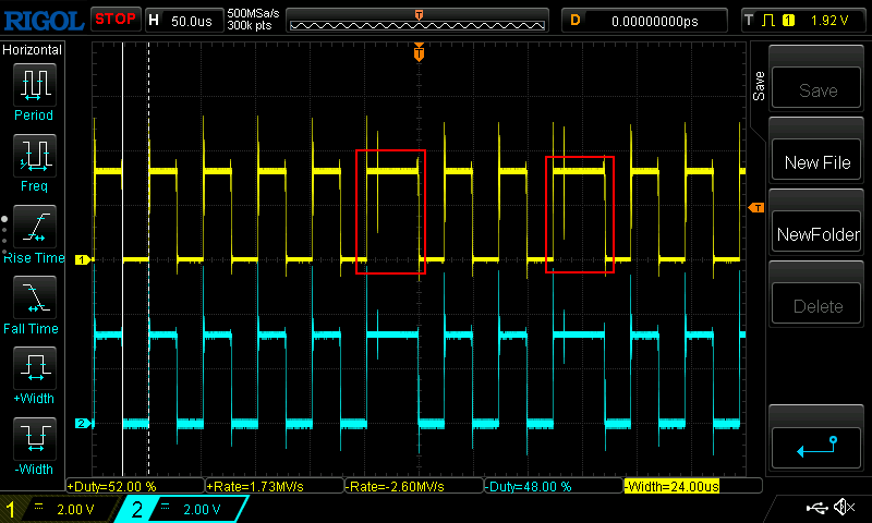
The following measurement shows correct PWM signals at 6 % DC 1000 ERPM Openloop operation at 30 V (CH1: High side signal on phase A, CH2: High side signal on phase B).
Length of each pulse is 25 µs ± 6%.

When increasing the voltage to 60 V (+ metal surface near PCB) sporadic incorrect pulses start to occur. On each incorrect pulse, the motor makes a clicking sound:
The length of individual pulses is around 50 µs, so exactly double the length of regular signals. In addition, we noticed some kind of instability of the software (e.g. output of terminal commands is truncated).
What we tried so far:
- Replaced STM32F405 (even different batches)
- Replaced all MCU capacitors
- Replaced gate drivers + capacitors
- Replaced and tested 8 Mhz crystal
- Logged TIM1 register values (CCR, ARR, CNT). No abnormalities found.
- Tested for MCU "brown out". BOR level 1 was never triggered.
It is strange, that wrong pulses have exactly twice the length. Is it possible that TIM1 is skipping some update events?
Do you have any ideas? Thank you for your support!
Fortunately, we were able to identify the problem in the meantime.
Apparently, VDDA's FerriteBead had caused problems. After it was desoldered and bridged, the issues disappeared. A bad solder joint can be ruled out (after installing a new ferrite bead, the problems were back).
FB1 = Murata BLM18AG102SN1D
It may also be due to the layout or placement:
Have you tried with a much larger capacitor on the vdda pin, say 10uF+. There might not be enough capacitance there for it work properly at higher frequency. I think the stm32 datasheet has 2.2uF for all the local decoupling and a larger capacitor as well. So I am surprised to see only 10nF on each of the VDD lines, for example I use 1uF at each VDD/VDDA pin and no ferrite bead.
Other problem since you say it's happening at higher voltage, is there is noise coupling onto that rail and the bead doesn't let the other bulk capacitance suppress it. So same solution, add more capacitance!
I would be interested to see what it looks like if you put a scope on that pin with the bead there.
Could also be the bead sanitizing your signal at vdda, but your current shunt amplifier references are no longer related to the vdda voltage. So you could be getting some offset problems there.
Thank alot for your input! You are right, the overall capacities seem really small (compared to the datasheet). We should improve this.
Ok, first of all I readded a new FB1 and tested VDDA.
CH1: VDDA vs. GND, CH2: High side PWM signal
Seems there are massive negative spikes > 2V:
Then I replaced C24 by 4,7uF (what was the largest capacity I had at hand for 0603).
Spikes were getting smaller and problematic voltage threshold shifted by some volts (60V instead of 55V):
As last, I had removed FB1 again and repeated the measurement.
The problems had disappeared, but the measurement did not really look different.
Other interesting observations (with FB1 in place):
- The issues can be caused when PA8-PA10 pins are touched, even if the amplifiers are physically disconnected.
- The issues can be massively reproduced if a cable is soldered to AGND and touches GND or the housing. If the housing is touched, the MCU will reset.
However, we will probably not install a ferrite bead in the future anymore and increase the capacities overall.