This is proof of concept design that im going to use later do make 16s (hopefully over 50a) Vesc for my e-bike.
Questions:
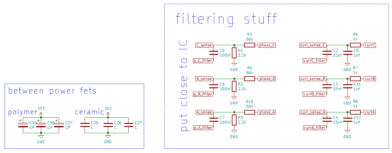
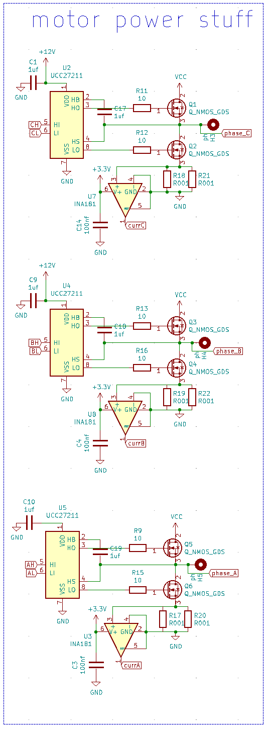
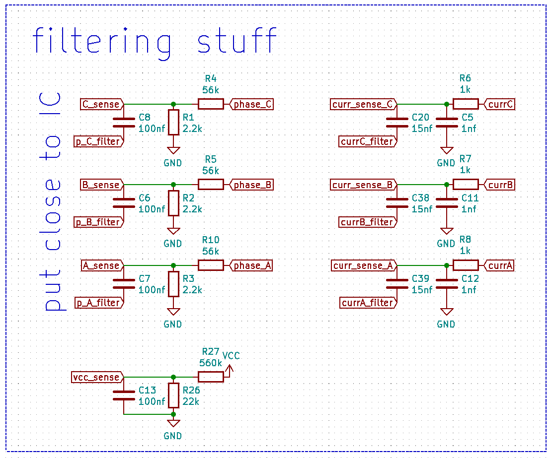
Q1: Are these phase and current filters beneficial enough to have them?
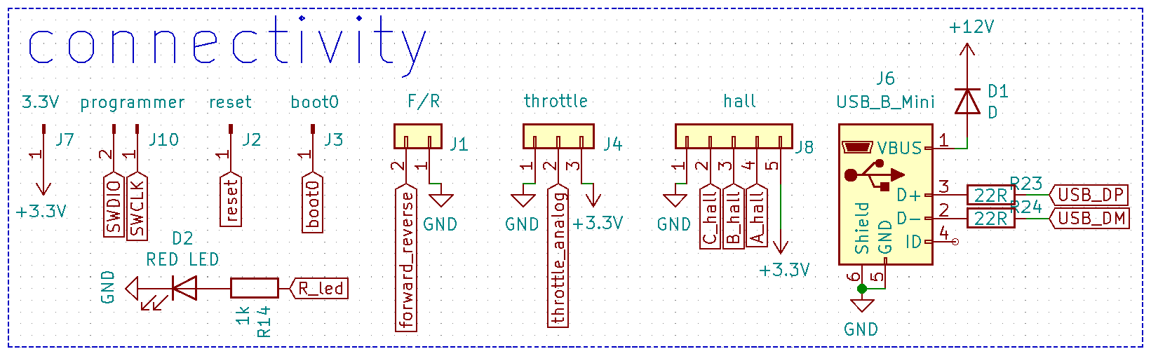
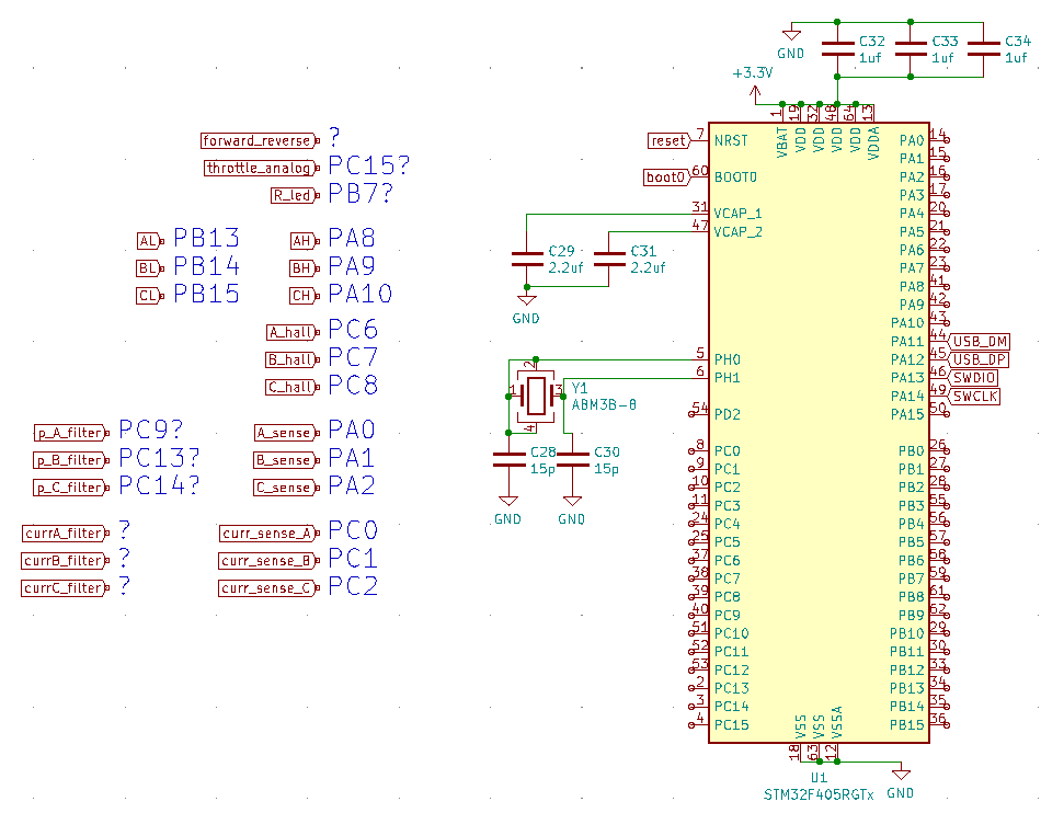
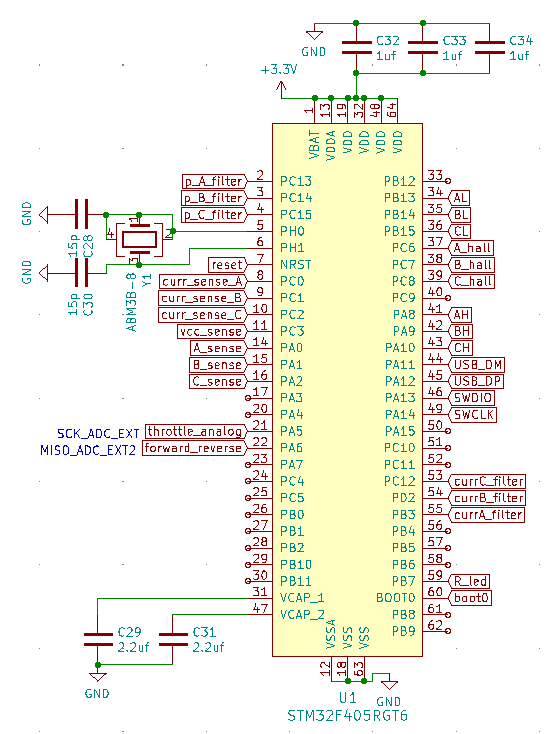
Q2: How to use USB without crystal oscillator?
This A200S V3 seems to have pulled it off. Or is it just betting on luck:
https://365.altium.com/files/C6F06825-C92D-11EB-A2F6-0A0ABF5AFC1B
https://teamtriforceuk.com/a200s-v3/
https://vesc-project.com/node/339?page=8
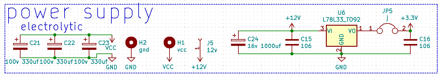
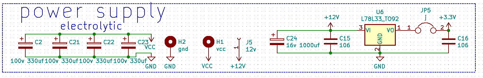
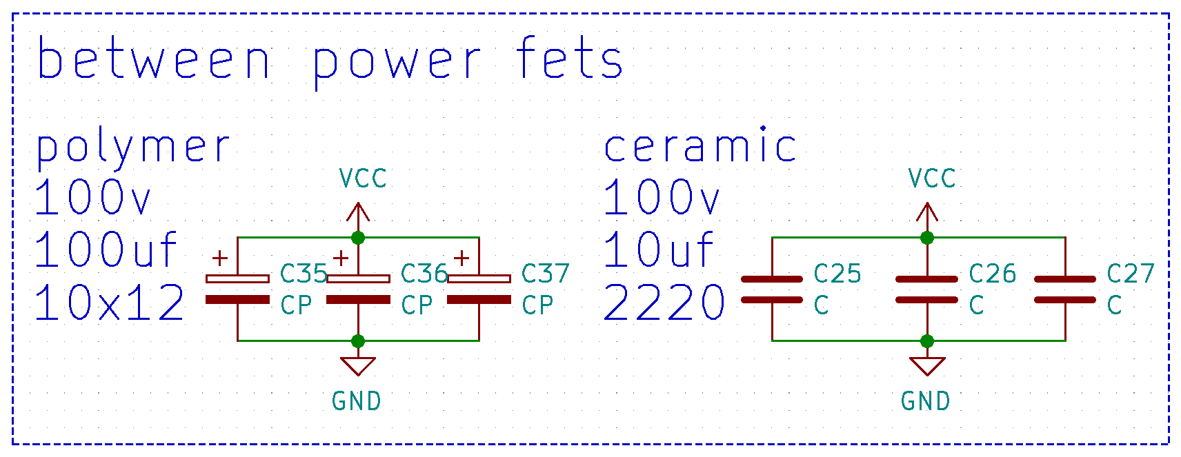
Q3: Recommended capacitance between power fets ? (120v fets 67.2v input)
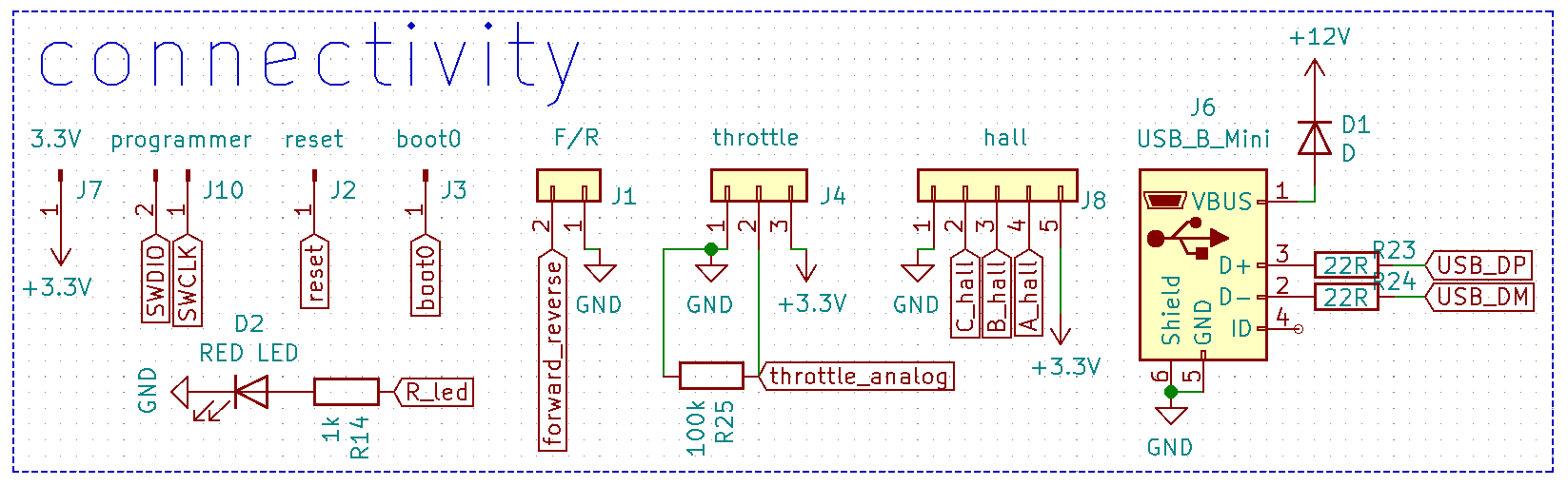
Q4: Which led pin should I use red or green?
Q5: Where is the file in which im supposed to enter all the settings like pin-out, disabling unnecessary peripherals or resistor divider ratios?
Q6: How do i set up these filter pins?
Q7: Can I use any pins for low side of the filtering capacitors? (e.g p_A_filter)
Q8: Any recommendations for connections to the STM32? (specifically the ones with "?")
Q9: So what I think the process of uploading the firmware to the empty STM32 is:
1. Download source from GitHub.
2. Edit configuration files to match my design.
3. Compile.
4. Upload using ST-LINK Utility and st link v2.
5. Set up motor configuration through USB.
Am I correct?
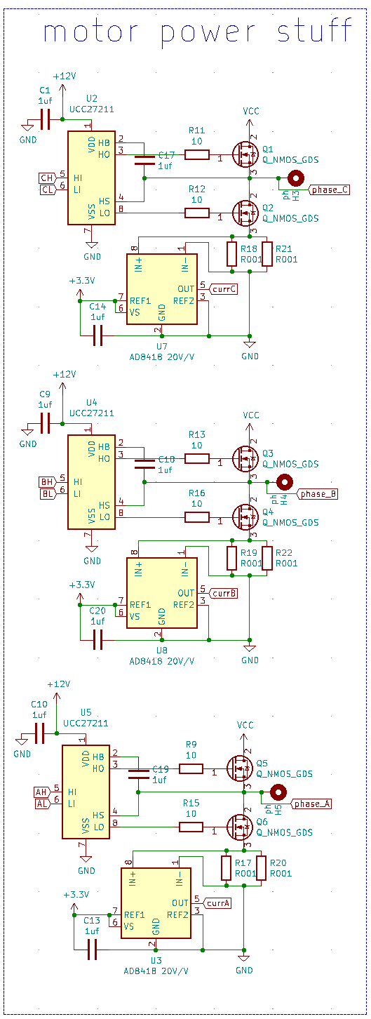
Current shunts are 1W resistors. I know that this is awkward but it's what I have on hand and it will do for test.
Somehow I lost my AD8418 amplifiers so I can replace them with something new. Any recommendations?
I need to keep my design as simple as possible because I will be milling it out from one-sided PCB.
(this is double-sided 0.3mm trace width)

Only thing I can comment on is the current filters. You seem to have taken the values from vesc 6 mkv. These values only really work well with phase shunts, not low side shunts. Better take values from a design with low side shunts. Reason is that the low side shunt only gets current when the low side mosfet is on. When the duty cycle of the phase is low there is not enough time for your liw pass filter to settle, causing large underestimation of the current.
Ps. Check out the unofficial vesc discord, there are many people who can help you there:
https://discord.gg/63af4YGuDU
1) Phase yes but not necessary if you're battling with layout on single side board. Current filters meaningless on low side shunts.
2) I'd advise you fit the crystal. It's not guaranteed to work without and probably won't at high temperature
3)1500uF+. No need for more than about 3000uF at your current levels. Include at least 20uF of ceramics really close to the FETs.
4) Copy the official hardware schematics where possible, but I think you can remap to any pins.
5) Create your own .c and .h in hwconf
6) Copy the relevant lines from the official hardware and other hardwares in the hwconf folder.
7) I believe so yes.
8) Copy the vesc 6 or 75/300 pins if possible for your layout.
9) Correct except you just type make upload, no need to use stlink utility (in Linux).
For low side shunts ina181a1
For phase shunts use ina240a1
Thank you, everyone for great advice.
I joined this discord server and it seems like people there know what they're doing.
Here is my updated schematic
added capacitors
added R25 to throttle to keep it at zero when nothing is connected
changed shunt amplifiers
selected capacitors
added input voltage divider for sensing input voltage (vcc_sense) cos Elwin knows what's up

changed some connections
After intense discussion on the discord server I changed current filters: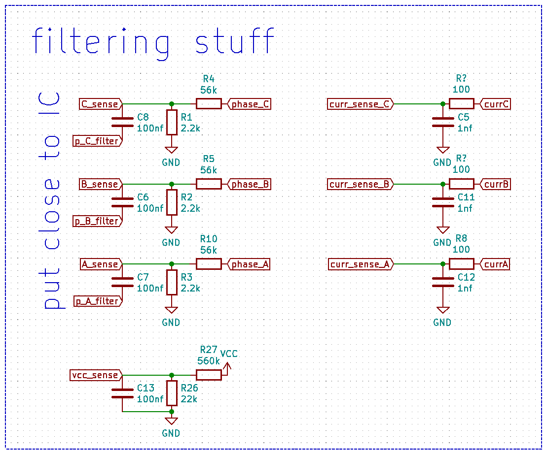
.
I think you will need to filter the hall signals.