Hello all,
Apologies in advance, I'm still new to electronics and am probably missing something simple.
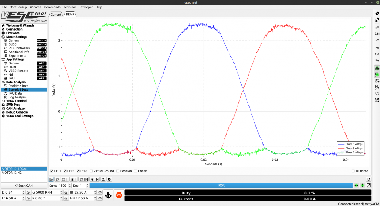
I'm working on a custom VESC-based piece of hardware but am running into an issue where the motor won't start. I've hacked up a Toyota Prius Inverter and got it connected to an STM32. The IGBT's are switching properly I'm able to connect with the VESC tool and such, and when attempting to run the motor in BLDC mode it cogs once a second, though it never actually starts. When rotating the rotor by hand the duty cycle goes up, however the RPM stays at zero. The "Sampled Data" page (taken when rotating shaft by hand) is showing some odd voltage readings, which I've attached below. It seems the negative swing of the waveform is getting truncated? This is where I'm honestly not sure what I'm doing.
Something I'm very confused about: I'm not sure what the STM32 is referencing each phase voltage against on both my hardware and the official VESC.
I understand that this is getting outside the scope of VESC support and more electronics support but I'd still appreciate any help I can get.
I should note that my current sensors aren't working right now, so current is reading as just zero. Not sure if that has any effect, but from what I understand it shouldn't matter in BLDC mode (though admittidely I understand very little here).
Some notes about the Prius Inverter, for those who are interested:
Why a Prius Inverter?
It has two 'motor controllers' (IGBTs, current sensors, temp sensors, etc). IE, you can control two motors with one physical unit.
It has a built in boost converter to boost battery voltage higher for the motors.
Each 'motor controller' can handle a ton of current. MG1 can handle 250 amps, MG2 can handle 350, constant.
It's split into two PCBs, the Logic PCB and the Power PCB. Replacing the Logic with your own as I've done is simple, so it's quite hackable.
They're everywhere and very cheap. Got mine for $50 at the local junk yard.
It's liquid cooled, so you can go pretty crazy as long as you keep it cool.
What's up with your logic replacement?
I whipped up a PCB in KiCad and had JLCPCB send some assembled boards to me. This is my second PCB ever so it's probably trash, but hey, the things sorta working.
Open source the boards?
Yeah, of couse. Once I get this stuff working I'd be glad to put all this up on github. Just don't drag me for how little I know about electronics/designing PCBs :(
What are you using this for?
I'm trying to build an electric go kart using some QS Motor 5000w hub motors. I don't like the Kelly controllers they came with so I figured I'd go a bit outside of my comfort zone and try something new.
Thanks in advance!
Probably want to post a schematic (even a snippet) and pic of your hardware setup.
Cool project!
You should be able to perform sampling and see everything working properly without needing to drive the motor or anything, the sampling is always going. For checking the current I find it easiest to externally push current across the sensor with something accurate and make sure that it actually reads what you expect (and in the right direction!) If it's the wrong way round it will actually have negative feedback and very quickly explode.
If you also turn on the Virtual ground on the sampling graph you will probably see that its actually at some voltage other than zero. I *think* that graph takes the common mode voltage (virtual ground) and then takes that away from the signals, so the voltage shown there probably isn't the actual voltage on the input. AFAIK
Do you have a scope to look at the signals going into the stm32?
Some photos / schematic showing how its connected up would help a ton.
I didn't even think to attach the schematic. My bad! It can be found here. A quick update: I think I resolved the truncated negative voltage issue. I've simply changed the voltage divider grounds to 1.65 volts. I'm not sure if this is the proper way to resolve the issue, but the voltage waveforms look proper now. I'm able to read RPM now as well. The motor is still cogging and refusing to spin, though. One thing I noticed is that while I'm spinning the motor, the rpm will switch from negative to positive, or vice versa. Like it's not sure which direction the motor is really going.
Notes about the current sensors: They're not shunts. They're CT sensors (I believe is what they're called.) Coils wrapped around each phase wire. Their schematics are based on another design by Damien Macguire, who previously reverse engineered this inverter. I'm having some power supply issues on the board which I believe are causing issues with the sensors. I'll be working on that next.
I do have a scope at my disposal, but I haven't used it a whole lot. Not sure what I'd even be looking for but I'm willing to learn :)
Edit: Here's a shot of the sampled data while we're at 10% duty. Virtual ground is all over the place and phases are all wonky?
And here's one of me spinning it by hand. Looks proper now I think! Now just need to figure out the cogging and virtual ground:
Alright, got some more stuff figured out. I was having some issues where the phase IGBTs were intermittently switching due to a pretty badly desoldered and resoldered connector. Finally got some stuff in the mail and got that sorted out it seems. The motor will now sort of spin at 18% duty, however it can't exactly pick a direction at first. After five or so seconds of it stuttering back and forth it'll start to slowly rotate. In some cases, it'll also stall. If I try to turn the duty up to something like 22%, it starts going a bit crazy, spinning back and forth with no apparent pattern. Screenshots of all cases are below. If anyone has any thoughts I'd be glad to hear them!
Here's a shot of when it's actually rotating:
Here's a shot of it stalled. Odd that phase 3 doesn't appear to be switching...
And here's a shot of it at a higher duty cycle. What the heck is going on here...