
I am having issues driving big motors with VESC firmware and IGBT (they explode when driven above 90% duty)
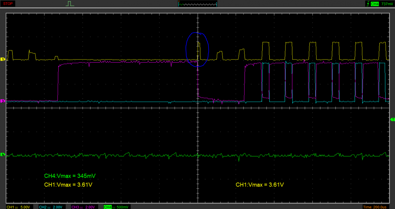
is that spike normal for trapezoidal modulation?
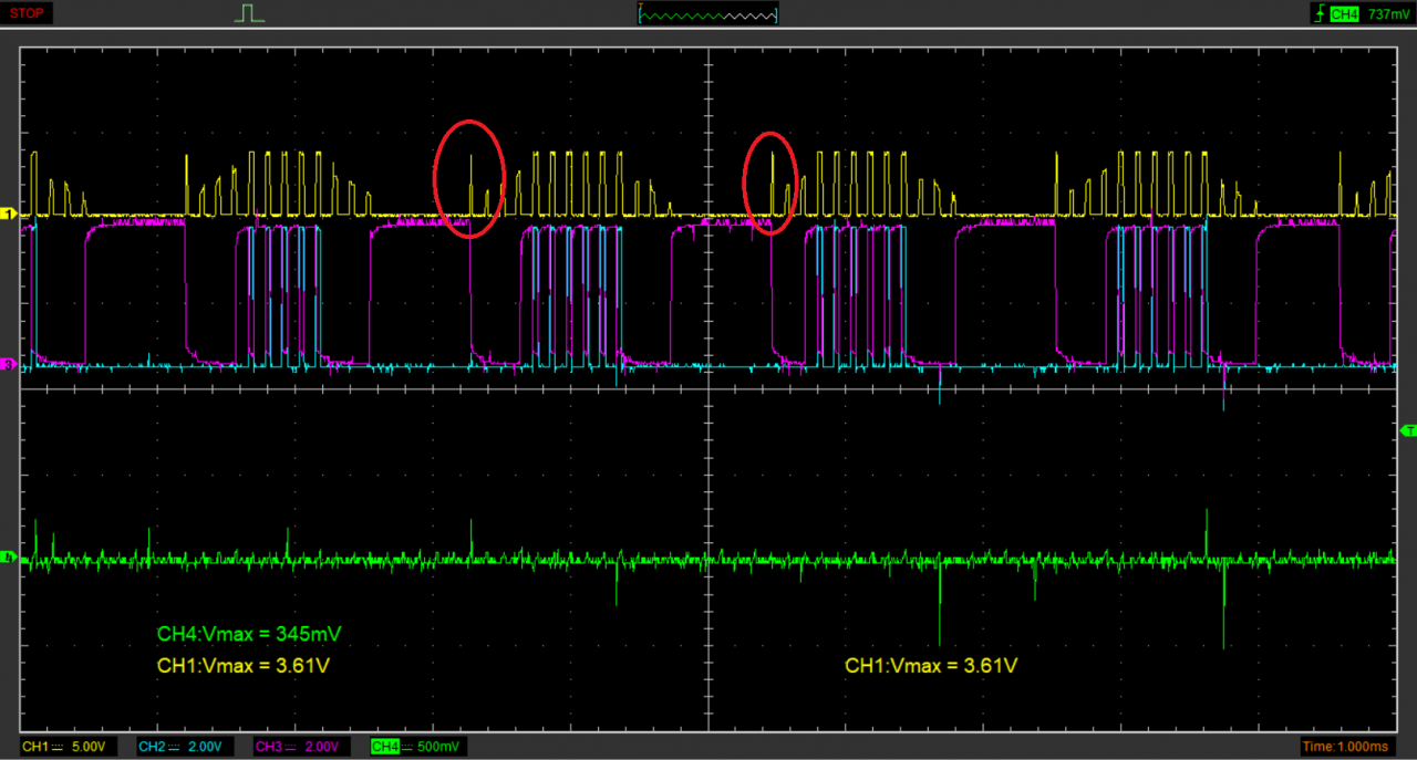
In the oszi capture the motor is running at low speed and no load, yes i am respecting the deadtime specs for this IGBT 2,4us
Signals explanation:
Yellow: Phase-Ground Voltage
Blue: high side Gate signal
Pink: low side Gate signal
Green: 0.5mA shunt detecting shortcircuits
Closer look
Hi, Show pls Your DC link voltage. Is there any spikes?? Spikes appear after low sie IGBT turn off. U can try increase ded time and watch what happend. Shunt measures may be affected by EMC. Try differential using two probes. Which IGBT explode?? Low or high side?? IGBT usually can withstand fiev us of permanent short circuit.
Regards Marcin
Your spike might be caused by self turn on from coupling of the low side gate signal, but I would expect that to be happening on the low side not high side.
So in that case the spike is probably back emf inductive spike from turning off the current quickly.
Which igbt blows?
Hello and thanks for your interest.
Answering your questions:
Im finding references of this weird initial pulse even in STM application notes! they just dont mind it, maybe is a normal thing?
page 16
hola!
Hi Javivi,
I think the spikes you see is the demagnetisation of the motor phase. I am not a motor expert, but it looks like that the demagnetisation results in a current in the direction of phase B (the green signal). As soon as both the bottom and top switch of phase B are turned off, the current of phase B runs through the body diode of the top switch to +Vbus. The higher the load current, the longer that this demagnetisation period will become. (off course this occurs in all phases subsequently)
This demagnetisation effect in case of outward current from the inverter will cause the (body) diode of the bottom mosfet conducting. You can see that in phase A just after turning off the PWMing.
These effects are normal and kind of belong to 'six step' BLDC control.
I hope this helps you to some extend.
Kind regards,
Roel