
Hello guys, I wish my first post in this forum were something more interesting....but well.....
I bought a generic VESC and updated it with the wrong firmware, now I can't connect to the VESC Tool and none of the leds are turning on.
What I did was just connecting the VESC to a 12v bench power supply, updated the firmware and tried to use an electric bicycle throttle to spin the motor.
Researching on the forum, it seams a common problem hahahaha but most people are able to resuscitate it using an STlink-v2.
So, my first problem is, how do I connect the STlink to the VESC????
And don't tell me it's just using the CLK, GND an IO pins because those pins don't exist on the VESC documentation :P
https://raw.githubusercontent.com/vedderb/bldc-hardware/master/design/PNGs/Schematic-1.png
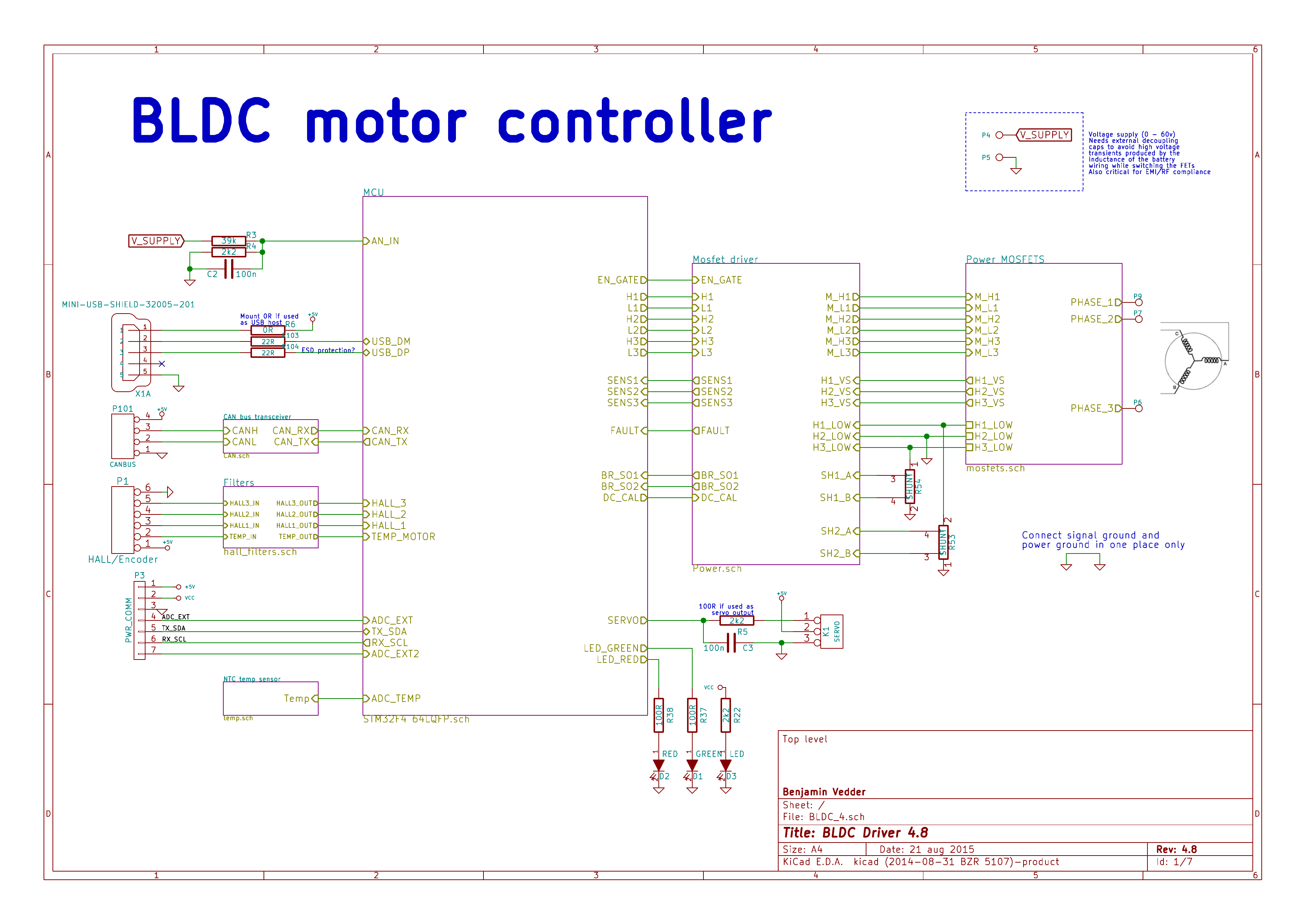
I know I'm supposed to use the PWR_COMM port, but as you can see, the pin names are different.
I'm an engineer and have a fair experience getting frustrated and burning quadcopter esc!
So you can get very technical if necessary be :P
But I'm fairly certain it's game over for this one........
Well aside from that being an image of the top page of the schematic, oh and the wrong HW version, have you tried looking here: https://github.com/vedderb/bldc-hardware/blob/master/design/BLDC_4.pdf?r...
And going to page 6 of 7, section 5B it shows a 6 way JST PH connector, with the following pin assignments; 1=VCC, 2=SWCLK, 3=GND, 4= SWDIO, 5= NRST, 6= NC
Alternatively: http://lmgtfy.com/?q=programming+VESC+STLink and check the images.
<breathing in heavily>
Ahhh.....the sour smell of passive aggressiveness in a new forum........
Well sir, I don't wish to antagonize you, but not everybody have extensive experience reading complex electronic diagrams and it's exactly this kind of attitude that disencourage new people from participating.
I actually have already read all that, I'm a week now researching the problem and from where I'm standing there is something missing or just plain wrong.
My VESC have a 7 pin connector that is different from all the other diagrams I found so far, the picture I attached is the only one that shows this 7 pin connector.
The manufacturer claims it is v4.12 and for what I saw so far it is the most common hardware version going around, but checking the correct diagrams for this version, there is no 7 pin connector anywhere and what I understood is that this is the COMM/Programing port.
So you can understand my confusion in trying to math your 6 pin, perfectly comprehensible but abstract in nature, connector with what I am actually looking in front of me.
http://vesc-project.com/
If you would tell us what kind of hardware you have, it would be easy to help. Is is it a 4.12?
I think Frazatto has 3 third party VESC based on 4.12
So the connectors are not the same to the original 4.12
I think you have to measure the connection between your 7Pin Connector and the STM32F405
https://easyeda.com/componentimage/STM32F405RGT6-4a21c9fcd92c4a568a36466...
So you can check which pins are SWDIO (PA13), SWCLK (PA14), NRST, GND and VCC with a multimeter
I think you may have misinterpreted my tone.
But I thought you were:
All that aside, if you attached a few pictures of your hardware/setup we could give you far more useful information.
Thanks guys, The manufacturer finally answered my pleas for help and guess what?!
They miss labeled the ports \o/
This is the correct map as they sent me and now I can check all the pins for what they really are supposed to do:
So the good news is that I can be sure now I broke the damn thing.
The STlink can't stablish a connection, none of the leds are turning on and none of the 3,3-5v pins have power.
They suggested for me to send it back so they can take a look.
What are the chances I burned the ARM processor itself?
The Power line is:
Battery 12V->DRV8301 (5V)->LDO 3.3V -> MCU
So, without the 5V, there are no 3.3V and so the MCU doesn't work. That means no ST Link connection.
Maybe the DRV is dead? The Voltage regulator in the DRV should work independent from all other Hardware.
See the DRV Datasheet to check the Voltages.
Did you try to power the MCU over the ST Link?
I love those SCRAM VESCs. I've had problems with the CAN bus IC & ground loops and the LM1117 3.3 regulator. If you have access to a lab power supply it may be worth trying to supply +3V3 directly to the output of the LM1117 (it has bigger pins so it's easier to do this than the STM32F405).
Ok ok things are getting weird.
Yes, I did found all the components you wanted me to test but, for no reason what so ever, I decided to try using only the minimum 8v on the bench power supply and for my complete amazement, one blue led turned on!!!!
I mean....that is freak.....why would it work with 8v and not 12???
Anyway, I tested with the VESC Tool but still no connection.
All the 3,3-5v pins have power, including the ARM processor power pins.
Stlink can stablish connection, but when I try "make upload" with the bldc-bootloader it gives me this message:
Can you make sense of it?
Good news everybody, on older hardware versions you NEED the reset pin to be connected and that was causing the timeout error on the programmer!!!!
So I re uploaded the, what I believe now is the correct, firmware and the bootloader using the original instructions:
http://vedder.se/2015/01/vesc-open-source-esc/
Now, with the STlink connected I get the blue and green led on (that is good right?), but the red link blinks twice for a wile and I can't find what it means.
Just using USB I get the blue light on but still no connection with the VESC Tool or the older BLDC Toll.
Any guesses what I should try next????
Just for desperation, I tried connecting the STlink and USB at the same time, VESCTool now is able to connect.
But why????
Power is restored with correct firmware, that is fine.
I don't believe I have burned the USB controller when I uploaded the wrong firmware, or it wouldn't be working at all.
Should I try to connect the motor and see what happens???
Well....I took the twisted road to solve the problem.
Tried to use STlink Utility with Wine on Linux since it has the feature to erase the whole flash, but it can't find the usb ports.
So I continued on to installing VirtualBox, made a Windows XP virtual machine and installed STlink Utility.
It worked great but still no connection with the VESCTool over USB alone.
So yea, most likely there is something burned in there.
I will now proceed to attach a motor and see what happens.
Hope this thread can help other people in the future o/