Hello Together,
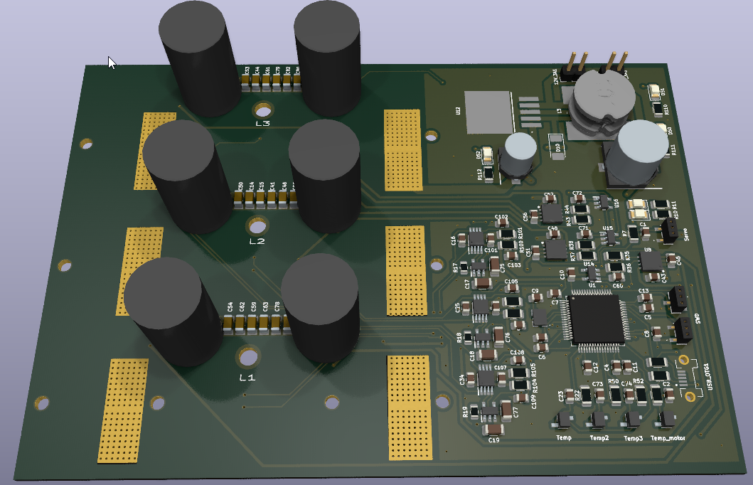
I would like to ask your help because I ran out of ideas :( Based on Benjamin's VESC 75/300 schematic I developed an own board for my RC speedboat.
I have only replpaced the followings:
FET --> Infineon IST006N04NM6AUMA1 --> 40V 475A, 0,0005 ohm (My maximum applied voltage is 21V)
Gate driver --> Infineon 2EDL8024GXUMA1 --> 4A sinc 4A source, 45ns
Current sense amplifier--> MAX40056TAUA+ --> 300kHz 20V/V
In BLDC mode it seems to work properly, the motor is heating up a bit faster then usually, but it is running well, and signals seems to be okay.:
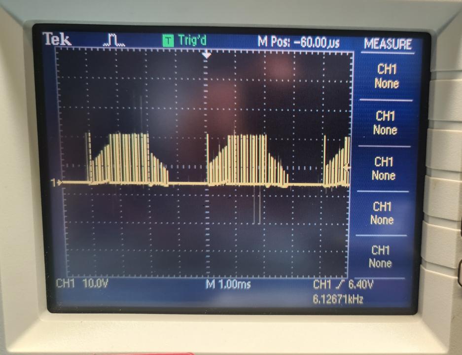
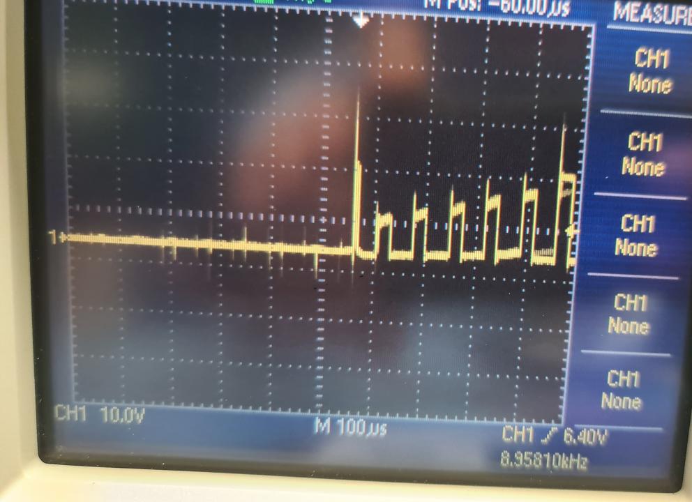
When I try to switch to FOC mode and run a motor FOC wizard, after I can hear a little noise from the motor but after one of my half bridge always die (low and high side together, so they short the Vin with the GND :S ).
I tried to configure three times (so I burned out 3 pairs of fets.. :S ) with different ways but the result was the same. If I set 8A current limit on the laboratory power supply the results was the same again (fets were not burned out but they went to short circuit. I have no idea how can it happen with 8A...
Could somebody give me ideas what could be the reason of this behavior? Now I am totally disappointed, because I spent a lot of time and money to develop this board without success :(
Thanks in advance,
Gergo
Schematic: VESC.pdf
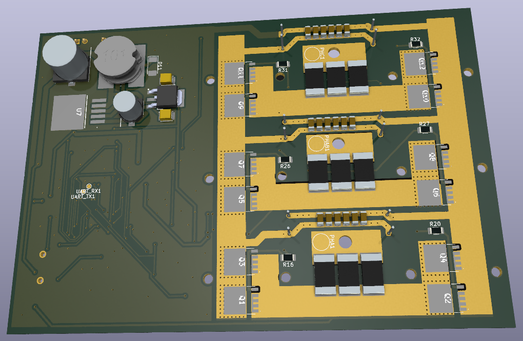
Mosfets are usually killed with voltage spikes exceeding mosfet voltage ratings. You are likely to have a lot of parasitics with those long and winding gate traces. If you want to keep them that long, you would need to use a lot of gate resistance to slow down switching. Start with 20R or so and see of that stops mosfets from blowing up. However, another big problem is that gate traces are routed through high current paths (for example, under the current shunts), so they are almost certain to pick up a huge amount of noise.
Yet, another issue is that your DC link capacitors may not be effective as they seem to be in a wrong place and have too thin connections. You need low impedance path from the DC link caps to smooth out the ripple.
That's what is visible on the surface. Likely more hidden issues. Expect to blow tons of mosfets before you figure things out.
NextGen FOC High voltage 144v/34s, 30kw (https://vesc-project.com/node/1477)